Difference between revisions of "Journal:Semantics for an integrative and immersive pipeline combining visualization and analysis of molecular data"
Shawndouglas (talk | contribs) (Cats) |
Shawndouglas (talk | contribs) m (pages to at) |
||
| Line 12: | Line 12: | ||
|pub_year = 2018 | |pub_year = 2018 | ||
|vol_iss = '''15'''(2) | |vol_iss = '''15'''(2) | ||
| | |at = 20180004 | ||
|doi = [http://doi.org/10.1515/jib-2018-0004 10.1515/jib-2018-0004] | |doi = [http://doi.org/10.1515/jib-2018-0004 10.1515/jib-2018-0004] | ||
|issn = 1613-4516 | |issn = 1613-4516 | ||
Latest revision as of 18:28, 22 October 2021
| Full article title | Semantics for an integrative and immersive pipeline combining visualization and analysis of molecular data |
|---|---|
| Journal | Journal of Integrative Bioinformatics |
| Author(s) | Trellet, Mikael; Férey, Nicolas; Flotyński, Jakub; Baaden, Marc; Bourdot, Patrick |
| Author affiliation(s) | Bijvoet Center for Biomolecular Research, Université Paris Sud, Poznań Univ. of Economics and Business, Laboratoire de Biochimie Théorique |
| Primary contact | Email: m dot e dot trellet at uu dot nl |
| Year published | 2018 |
| Volume and issue | 15(2) |
| Article # | 20180004 |
| DOI | 10.1515/jib-2018-0004 |
| ISSN | 1613-4516 |
| Distribution license | Creative Commons Attribution-NonCommercial-NoDerivatives 4.0 International |
| Website | https://www.degruyter.com/view/j/jib.2018.15.issue-2/jib-2018-0004/jib-2018-0004.xml |
| Download | https://www.degruyter.com/downloadpdf/j/jib.2018.15.issue-2/jib-2018-0004/jib-2018-0004.xml (PDF) |
Abstract
The advances made in recent years in the field of structural biology significantly increased the throughput and complexity of data that scientists have to deal with. Combining and analyzing such heterogeneous amounts of data became a crucial time consumer in the daily tasks of scientists. However, only few efforts have been made to offer scientists an alternative to the standard compartmentalized tools they use to explore their data and that involve a regular back and forth between them. We propose here an integrated pipeline especially designed for immersive environments, promoting direct interactions on semantically linked 2D and 3D heterogeneous data, displayed in a common working space. The creation of a semantic definition describing the content and the context of a molecular scene leads to the creation of an intelligent system where data are (1) combined through pre-existing or inferred links present in our hierarchical definition of the concepts, (2) enriched with suitable and adaptive analyses proposed to the user with respect to the current task and (3) interactively presented in a unique working environment to be explored.
Keywords: virtual reality, semantics for interaction, structural biology
Introduction
Recent years have seen a profound change in the way structural biologists interact with their data. New techniques that try to capture the structure and dynamics of bio-molecules have reached an extraordinary high throughput of structural data.[1][2] Scientists must try to combine and analyze data flows from different sources to draw their hypotheses and conclusions. However, despite this increasing complexity, they tend to rely mainly on compartmentalized tools to only visualize or analyze limited portions of their data. This situation leads to a constant back and forth between the different tools and their associated environments. Consequently, a significant amount of time is dedicated to the transformation of data to account for the heterogeneous input data types each tool is allowing.
The need for platforms capable of handling the intricate data flow is then strong. In structural biology, the numerical simulation process is now able to deal with very large and heterogeneous molecular structures. These molecular assemblies may be composed of several million particles and consist of many different types of molecules, including a biologically realistic environment. This overall complexity raises the need to go beyond common visualization solutions and move towards integrated exploration systems where visualization and analysis can be merged.
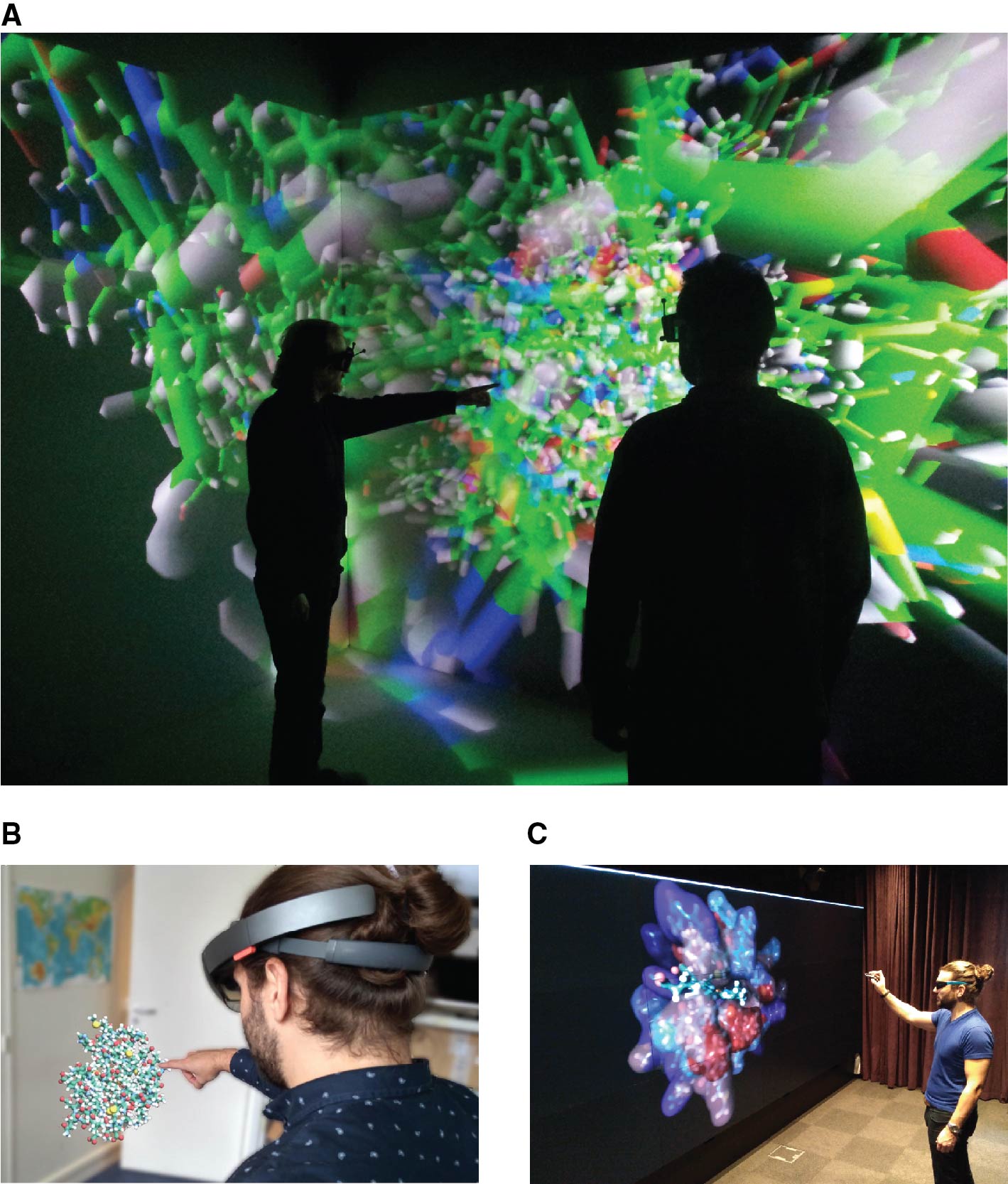
Immersive environments play an important role in this context, providing both a better comprehension of the three-dimensional structure of molecules, and offering new interaction techniques to reduce the number of data manipulations executed by the experts (see Figure 1). A few studies took advantage of recent developments in virtual reality to enhance some structural biology tasks. Visualization is the first and most obvious task that was improved through new adaptive stereoscopic screens and immersive environments, plunging experts into the very center of their molecules.[3][4][5][6][7] Structure manipulations during specific docking experiments have been improved thanks to the use of haptic devices and audio feedback to drive a simulation.[8] However, if 3D objects can rather easily be represented and manipulated in such environments, the integration of analytical values (energies, distance to reference, etc.)—2D by nature—leads to a certain complexity and is not a solved problem yet. As a consequence, no specific development has been made to set up an immersive platform where the expert could manipulate data coming from different sources to accelerate and improve the development of new hypotheses.
|
This lack of development can also be partly explained by the significant differences between the data handled by the 3D visualization software packages and the analytical tools. On one side, 3D visualization solutions such as PyMol[9], VMD[10], and UnityMol[11] explore and manipulate 3D structure coordinates composing the molecular complex that will be displayed. The scene seen by the user is composed of 3D objects reporting the overall shape of a particular molecule and its environment at a particular state. This scene is static if we are interested in only one state of a given molecule, but is often dynamic when a whole simulated trajectory of conformational changes over time is considered. Analysis tools, on the other side, handle raw numbers, vectors, and matrices in various formats and dimensions, from various input sources depending on the analysis pipeline used to generate them. Their outputs are graphical representations of trends or comparisons between parameters or properties in 1 to N dimensions formatted in a way that experts can quickly understand and use such information to guide their hypotheses.
Some of the aforementioned software do provide tools to gather analyses as static plots aside the 3D visualization space. Interactivity is limited and flexibility mainly depends on the user capability to create and tune scripts to improve the information displayed. We believe that a major improvement of tools available today would bring into play a scenario where the 3D visualization of a molecular event is coupled to monitoring the evolution of analytical properties, e.g., sub-elements such as distance variations and progression of simulation parameters, into a single working environment. The expert would be able to see any action performed in one space (either 3D visualization or analysis) with a coherent graphical impact on the second space to filter or highlight the parameter or sub-ensemble of objects targeted by the expert.
We have developed a pipeline that aims to bring within the same immersive environment the visualization and analysis of heterogeneous data coming from molecular simulations. This pipeline addresses the lack of integrated tools efficiently combining the stereoscopic visualization of 3D objects and the representation/interaction with their associated physicochemical and geometric properties (both 2D and 3D) generated by standard analysis tools and that are either combined to the 3D objects (shape, colour, etc.) or displayed on a dedicated space integrated in the working environment (second mobile screen, 2D integration in the virtual scene, etc.).
In this pipeline, we systematically combine structural and analytical data by using a semantic definition of the content (scientific data) and the context (immersive environments and interfaces). Such a high-level definition can be translated into an ontology from which instances or individuals of ontological concepts can then be created from real data to build a database of linked data for a defined phenomenon. On top of the data collection, an extensive list of possible interactions and actions defined in the ontology and based on the provided data can be computed and presented to the user.
The creation of a semantic definition describing the content and the context of a molecular scene in immersion leads to the creation of an intelligent system where data and 3D molecular representations are (1) combined through pre-existing or inferred links present in our hierarchical definition of the concepts, (2) enriched with suitable and adaptive analyses proposed to the user with respect to the current task, and (3) manipulated by direct interaction allowing to both perform 3D visualization and exploration as well as analysis in a unique immersive environment.
Our method narrows the need for complex interactions by considering what actions the user can perform with the data he is currently manipulating and the means of interaction his immersive environment provides.
We will highlight our developments and the first outcomes of our work through three main sections: the first section attempts to provide a complete background of the usage of semantics in the fields of VR/AR systems and structural biology. In the second section we will describe and justify our implementation choices and how we linked the different technologies highlighted in the previous section. Finally, in a third section, we will show several applications of our platform and its capabilities to address the issues raised previously.
Related works
We present here the state of the art in the two fields related to this paper: the semantic formalism chosen to represent the data and how semantic representations are applied in bioinformatics.
Semantic modeling formalism and semantic web
From classical logic to description logic, from which was derived the "conceptual graph" representation introduced by Sowa[12], many semantic formalisms were used to embed knowledge into applications in order to query and perform reasoning about them.
The conceptual graph formalism represents concepts and properties such as connected graphs and allows complex operations on them. However, it quickly reaches some limitations in terms of performances and implementation flexibility. Classical logic is another well-known formalism but is not broadly used in biology and suffers a lack of implementation tools and libraries. A semantic network limits itself to the representation of concepts and their relations through directed or undirected graphs. It is lacking the possibility to reason over the concepts and their links, reasoning that our intended platform needs. The different requirements of our platform, coupled with our aim to make it as generic as possible, made us choose to use description logics as a formalism for knowledge representation and more precisely the semantic web as underlying standard for the creation of our ontology and the associated knowledge base.
The semantic web has been created by the World Wide Web Consortium under the lead of Tim Berners-Lee, with the aim to share semantic data on the web.[13] It is broadly used by the biggest web companies to uniformly store and share data. It belongs to the family of description logics that use the notions of concepts, roles, and individuals. The concepts are represented by the sub-ensemble of elements in a specific universe, the roles are the links between the elements, and the individuals are the elements of the universe. Each layer of the semantic web (ontology, experimental data, querying process, etc.) has been associated to a language or a format.
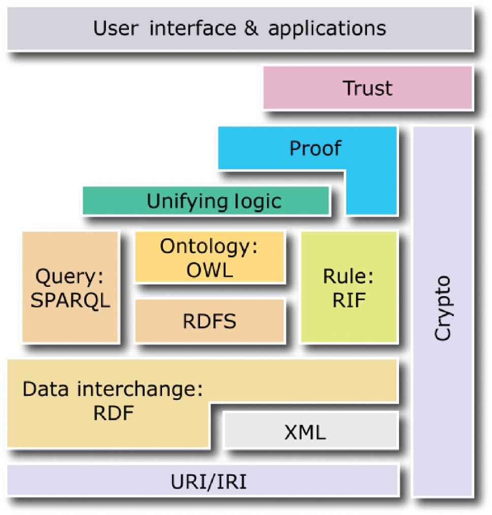
The following four standards create the core of the semantic web and act as the layers evoked previously: the Resource Description Framework (RDF)[14], the Resource Description Framework Schema (RDFS)[15], the Web Ontology Language (OWL)[16], and SPARQL.[17] Whereas the first three standards enable semantic descriptions of data in the form of ontologies and knowledge bases, the last standard enables queries to ontologies and knowledge bases (see Figure 2).
|
RDF is a data model, which allows the creation of statements to describe resources. Each statement is a triple comprised of: a subject (resource described by the statement), a predicate (property of the subject), and an object (literal value or resource identified by a URI, which describes the subject). An example of a triple is: <#Molecule, #has-charge, -1>
RDFS and OWL are semantic web standards that extend the expressiveness of RDF by providing additional concepts. RDFS provides hierarchies of classes and properties as well as property domains and ranges. OWL, built upon RDF and RDFS, provides symmetry, transitivity, equivalence, and restrictions of properties as well as operations on sets of resources. In turn, SPARQL is a query language for ontologies and knowledge bases built using RDF, RDFS, and OWL. Conceptually, in terms of possible operations on data, SPARQL is similar to SQL, as it enables data selection, insertion, update, and removal.
In the semantic web, two types of statements are distinguished. Terminological statements (T-Box) specify conceptualization, classes and properties of resources[18], without describing any particular resources. Assertion statements (A-Box) specify utilization, particular resources (also called individuals or objects), which are instances of classes described by properties with particular values assigned. For example, a T-Box specifies different classes of molecules (different chemical compounds) and properties that can be used to describe them (e.g., charge and the number of neutrons), while an A-Box specifies particular molecules (instances of the classes) with given charges. In this paper, an ontology is a T-Box, while a knowledge base is the union of a T-Box and an A-Box. Ontologies and knowledge bases constitute the foundation of the semantic web across diverse domains and applications. In particular, ontologies can specify schemes of molecular descriptions, while knowledge bases—particular descriptions (instances of such schemes) with individual objects—are used for analysis and visualization. Due to the use of the standards encoded in XML or equivalent formats, ontologies and knowledge bases are interpretable to software, making them intelligible to users. Moreover, since RDFS and OWL are built upon description logics, which are formal knowledge representation techniques, ontologies and knowledge bases can be subject to reasoning, which is a process of inferring implicit (tacit) properties of resources (which have not been explicitly specified by the author) on the basis of their explicitly specified properties.
For instance, from the following triples explicitly specified by the content author:
<my:is-composed-of> <my:is-a> <owl:TransitiveProperty>
<my:Protein> <my:is-composed-of> <my:Amino-acid>
<my:Amino-acid> <my:is-composed-of> <my:Atom>
the following statement can be inferred by software:
<my:Protein> <my:is-composed-of> <my:Atom>
Here, thanks to the definition of property “is-composed-of” as transitive, we can infer that atoms, that compose amino acids, compose as well a protein since amino acids compose proteins. The second statement does not need to be added to the ontology since automatically inferred. This reduces significantly the number of statements to store in the database and potentially allows for more complex inferences.
Ontologies in bioinformatics
On the application side, the use of ontologies in order to standardize knowledge in scientific fields underwent an important and spontaneous growth at the end of the 1990s.[19] Bioinformatics, tightly anchored in structural biology, has used ontologies for a long time. The most significant example is the fast-growing genomic field, in which it became impossible to handle data flow without a proper and standardized organization of the data.[20] The tool Gene Ontology[21] regroups genomic data into a uniform format and a knowledge base. Currently, it is one of the most referred to ontologies in the literature. Rabattu et al.[22] propose an approach to spatio-temporal reasoning on semantic descriptions of an evolving human embryo. Several biological databases or organizations such as UniProtKB and the Open Biomedical Ontologies[23] provide ways to access data or ontologies under RDF or OWL format to allow their use in expert tools or specific pipelines. One can also note the open-source project Bio2RDF[24] that aims to build and provide the largest network of "Linked Data for the Life Sciences" using semantic web approaches.
Only a few expert software packages based on ontologies have been developed for structural biology. Avogadro[25] and DIVE[26] appear as exceptions, implementing, in different ways, a semantic description of data that can be manipulated in these environments. Avogadro uses the Chemical Markup Language (CML)[27] as the format for describing data semantics, and it adds a semantic description layer on top of the data being described. However, the tool leverages neither ontologies nor other knowledge representation formalisms, thus it does not permit reasoning on the described data.
DIVE partially creates ontologies and datasets derived from the input data upon loading. Pre-formatted input in a row/column representation are converted into a SQL-like structure where rows are individuals and columns properties. This data representation conforms to a common data model that the software libraries use. Therefore, creation of links between data values and concepts are possible, and different DIVE components for data presentation (analyses, 3D visualization, etc.) as well as links and relationships between dataset elements can be queried. In addition, DIVE includes a powerful and generic ontology creator directly depending on the type of the input data. However, reasoning on ontologies in DIVE is limited to inheritance between classes. Consequently, only a few ontological relationships are available: is-a, contains, is-part-of, and bound-by. There is no notion of cardinality or logical operators to define the concept classes. Then, it is not possible, for instance, to force the presence of a property, or to impose that only a fixed number of values are associated to a specific property (e.g., a molecule must have at least one atom, an Alanine side-chain has a minimum of three atoms and a maximum of four atoms, etc.). These limitations render the DIVE environment insufficient to solve the problem stated in this paper.
Using a semantic representation to efficiently store, query, and link heterogeneous structural biology data
Several important choices have been made to integrate the different technologies required for the establishment of a platform that would allow a proper 3D immersion of users together with an accurate and intelligent way to interact with their data. Our platform heavily relies on the ontology/knowledge base couple. The way to represent and access the data present in the databases is of a crucial importance, and this point led us to ask ourselves the question of the most appropriate formalism for the data representation.
Knowledge formalism choice
The formalism of knowledge representation used in our approach must address the following three rules to properly fit our platform needs:
- Hierarchical data representation via concepts and properties
- Advanced reasoning possibility in order to extend the ontology or the dataset ruled by the ontology
- Efficient query time on the data to stay within interaction time
We mentioned previously that several formalisms exist to create ontologies and define databases. A quick comparison of these formalisms, complementary to their introduction in the previous section, can be found in Table 1.
| ||||||||||||||||||||||||||||||||||||
Our first implementation of a semantic representation of knowledge in molecular biology was applied through conceptual graphs (CG) within Cogitant’s software.[28] The use of CGs through the Cogitant API quickly proved to be incompatible with the constraints of the interactive context. This limitation had already been highlighted by the work of Yannick Dennemont[29] with the Prolog CG API, limitations confirmed by our own experience with the Cogitant library in C++. The need for high performance imposed by the interactive context has led us to the path of description logic and semantic web for the representation of knowledge and the efficient extraction of information within a massive fact base to support Visual Analytics functionalities in molecular biology.
Ontology for modeling of structural biology concepts
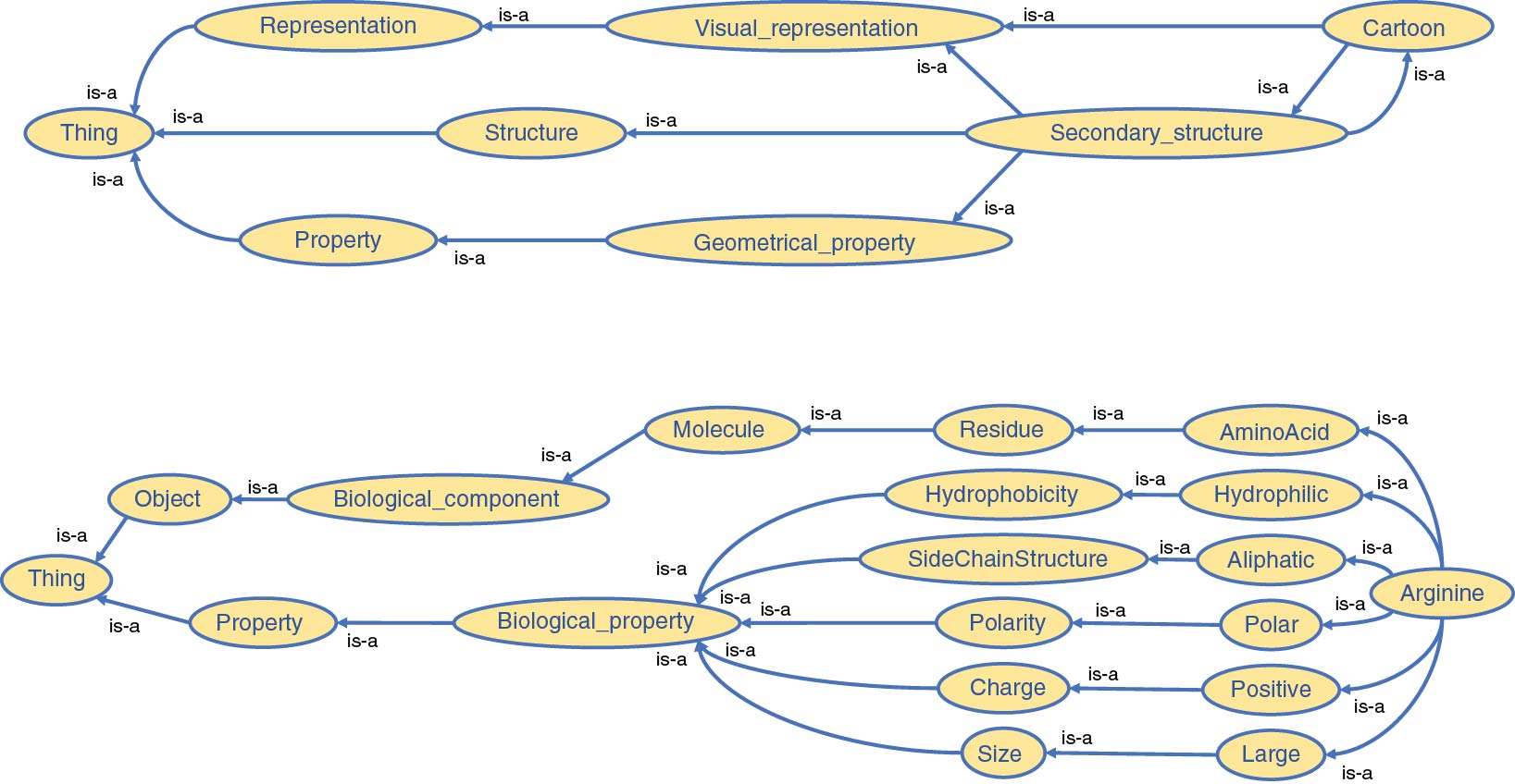
An OWL-based ontology was implemented as the core of the platform, thereby creating a broad description of concepts an expert has to interact with during his/her visualization and analysis activities. We previously mentioned that several bio-ontologies already exist. We extended one of them, a bio-ontology describing amino acids and their biophysical and geometrical properties to define the molecular objects and principles manipulated in structural biology. Each component structuring molecular complexes and each associated property coming from various common bio-informatics tools have been systematically defined and added to this ontology. However, since needs may vary, we have designed this ontology such that it could easily be updated and enriched with new concepts. A tiny subpart of our ontology is illustrated in Figure 3. Our ontology has been designed around five categories, addressing five different parts of our platform:
- Biomolecular knowledge – Field-related concepts and objects in structural biology
- 3D structure representation – Concepts related to the representation and visualization of 3D molecular complexes
- 2D data representation – Concepts related to the representation of numerical analyses and their results
- 3D interactions – Concepts related to the interactions in 3D environments
- 2D interactions – Concepts related to the interactions in 2D environments
|
The separation of the categories does not induce the absence of relationships between them. For instance, the “Atom” concept belongs to the "Biomolecular" knowledge category but is directly linked to the “Sphere” concept from 3D structure representation. The whole network of connections will then permit reasoning on the ontology in order to support the advanced interactivity level required in our platform.
Concepts and properties among the 3D structure representation and 2D data representation categories gather the graphical elements that allow for the representation of the "Biomolecular" knowledge category. Shape, colors, but also graph types are notions defined in these two categories. It is worth noting that analytical concepts are defined by graphical or abstract elements that play a role in the creation and visualization of an analytical result. However, we voluntarily chose not to define the different calculations and analyses related to molecular simulation data because of their high complexity and their heterogeneous nature varying significantly between the range of available specialized tools. This choice does not imply that the results of such analyses will not be used among the platform, merely that it is not relevant to include their definition in the ontology. The values of their results are nevertheless defined in the ontology under the form of properties of the individuals they bring to play.
In addition to the biomolecular concepts and representations previously cited, we also defined every concept around the interaction between the user and the data they will directly or indirectly manipulate. These interactions include commands proposed by most of the common visualization software packages and analysis tools.
Our full ontology is publicly available online.
Storing molecular data linked by a structural biology ontology
Once we set up our ontology, it was possible to feed the database by adding biological information gathered by the expert. The new information has to fit the vocabulary and classification defined by the rules present in the ontology in order to be adequately stored in the database. This combination of ontology and knowledge base will form the RDF database (as illustrated later in this article in Figure 6).
The description of a molecular system is constructed from the analysis of any biological information that can be described by a character chain or a value and that corresponds to a concept or property identified in the ontology. Each information will be exhaustively gathered in the RDF database as triples. Within the scope of our study, we focused on numerical molecular simulations. These simulations output time series of static snapshots of the molecular system at a regular time step. The Hamiltonian of the simulated model will drive the system towards specific states that experts try to decipher in order to understand underlying molecular mechanisms. The whole simulation creates a trajectory where each state, at a precise time, is associated to a snapshot. Our ontology defines a snapshot by the "model" concept. A model gathers all the atom coordinates of the molecular system at a defined time step. In order to distinguish the different components of a system, these components are identified by "chain," another concept of our ontology. Each chain in the system is composed of a sequence of "residues" (also known as amino-acids in proteins). The different inference rules present in the ontology save us to specify all the links between the different hierarchical components of a specific model explicitly. As a result, a residue that belongs to a specific chain will be automatically associated to the corresponding model where the chain appears. Similarly, group of atoms, the smallest entities of a molecular structure at our scale, constitute residues and are then directly linked to chains and models.
Every geometrical property (position, angle, distance, etc.), physicochemical property (solvent accessibility, partial charge, bond, etc.), or analytical property (interaction energy, RMSD, temperature, etc.) is then integrated in the database and associated to individuals created from 3D structures (Model/Chain/Residue/Atom) for each step of the simulation. As a reminder, any individual is an instance of concepts defined in the ontology. Individuals and their properties form the population of the molecular database.
Using semantic queries to support direct interactions for a new generation of molecular visualization applications
Once all data has been integrated in the RDF database, it is necessary to set up an interrogation system able to retrieve the data for visualization and processing following interaction events in the working space. Our implementation of the query system mainly relies on the usage of SPARQL, as introduced before, and provides several ways to address the different needs of our platform.
From vocal keywords to application command
The richness and flexibility of SPARQL queries allowed us to design a keyword to command interpretation engine that aims to transform a list of keywords into a comprehensive application command triggering an action in the working space.
One of the most-widely used interactive techniques in immersive environments is the vocal command. Based on a vocal recognition process, it consists in translating a sentence or a group of words said by the user into an application command. Vocal commands have the strong advantage that they can be associated with gestures to express complex multimodal commands.
Most of the actions identified in our platform involve a structural group designated by the expert. These structural groups can be characterized by identifiers having a biological meaning (for example residue ids are, by convention, numbered from one extremity of the chain to the other), unique identifiers in the RDF database, or via their properties. The interpretation of commands vocalized by the expert with natural language using a specific field-related vocabulary requires a representation carrying the complexity of the knowledge and linking the objects targeted by the user to the virtual objects involved in the interaction.
For this purpose, we set up a process that takes as input a vocal command of the user and translates it into an application command for the operating system. This procedure can be divided in three main parts:
- Recognition of keywords from a vocal command
- Keyword classification into a decomposed command structure
- Creation of the final and operational command
Our conceptualization effort and the use of the ontology mainly focused on the second part. Parts one and three are more implementation oriented and will not be deeply described.
Keyword recognition
We are using the keyword spotting capability of Sphinx[30], a vocal recognition toolkit, to recognize keywords. Based on a dictionary created from the ontology list of concepts, it aims to detect any word said by the user that would match a word present in the dictionary.
Keyword classification
Each keyword recognized in the previous step is assigned to a category. This classification is based on our ontology splitting, which identifies five categories of words that can be found in a vocal command, semantically modeled as:
- Action
- Component
- Identifier
- Property
- Representation
This classification is achieved through successive SPARQL queries to the ontology. Action, Component, Property, and Representation categories have their own concepts and can be identified by a unique word (“Hide,” “Chain,” “Charged,” “Sphere,” etc.). At the opposite, the Identifier category is linked to a concept instance from the Component category. A biological identifier is very likely to be redundant because of the repetition of the molecular system at each time step. Therefore it is mandatory to pair an identifier with a component in the keywords in order to validate its presence. Without component, any identifier is withdrawn from the list. If the identifier and the associated component exist in the database, the couple is validated.
SPARQL commands use the ASK operator to define whether a keyword belongs to a category or not. This operator takes one or several triples and returns a boolean that reflects whether the ensemble of triples is true or not with respect to the database. Some examples of queries can be found below:
ASK {my:Hide rdfs:subClassOf my:Action}
ASK {my:Alanine rdfs:subClassOf my:Biological_component}
ASK {my:Cartoon rdfs:subClassOf my:Representation}
ASK {my:Aliphatic rdfs:subClassOf my:Property}
Reasoning and inference rules are automatically used in SPARQL queries. For instance, the following query:
ASK {my:Alanine rdfs:subClassOf my:Biological_component}
will output true despite the absence of an explicit direct link between the two concepts (Alanine and Biological_component) since AminoAcid, Residue and Molecule are located between the two concepts (see Figure 4).
|
Command creation
Once each keyword is validated and associated to a category, e.g., identified as a concept of the database (or as an individual for identifiers) and eventually grouped with another keyword, it forms a syntactic group. Each syntactic group carries an information corresponding to a specific part of the application command.
In our platform, a vocal command is composed by a succession of syntactic groups linked between them to create an action query to the immersive platform. It is possible to describe the type of command that was defined in the following manner:
action [parameter]+, ( structural_group [identifier]+ )+
Syntactic groups between [] are optional, whereas others are mandatory. The + indicates the possibility to have 0, 1, or several occurrences of the syntactic group. Finally, () indicates a bloc of syntactic groups. This command architecture is present in our ontology under the form of pre-required concepts associated to the action concepts. For instance, the action concept "Color" requires a property of "Colors" type and a structural component to work with. These elements of information are then stored in the ontology, rendering them automatically checkable by the engine to detect whether all requirements are fulfilled for a specific action. This feature simplifies the definition of other actions in the ontology as the changes that have to be applied to the engine are minimal, typically either no or minor changes. The checking process will stay the same as long as the action is well-defined within the ontology.
At the same level as for an action, a structural group is always mandatory to trigger a command. The different ways to obtain a structural sub-ensemble are:
- Component only: every individual that belongs to the concept will be taken into account
- Combination of a component and an ensemble of identifiers: coherency checking between component and identifiers
- Property only: every individual that possesses the property will be taken into account
- Combination of a component and a property: coherency checking between component and property
The structural group always refers to a group of individuals in order to disambiguate the results between the commands. This disambiguation implies that final commands are more complex. The hierarchical classification between structural components (Model/Chain/Residue/Atom) has a significant impact on the results of a given command. Indeed, the nature of structural components targeted by an action will be compared to the nature of the structural components currently studied. Depending on whether the command individual will be of a higher or lower hierarchical order, the command might trigger an action either on a subpart of the displayed scene (for lower classified individuals) or as a scene composition changer (for higher or equal classified individuals). For instance, if only two models are studied when a vocal command is transmitted, putative amino acids individually targeted by an action will be the ones that belong to the two displayed models. If the individuals targeted by the command action would have been models, different from the displayed ones, an update of the displayed molecular complexes would have occurred first.
Once the different checks for the command coherency and validity have been carried out, the command is sent to both spaces (visualization and analysis) in order to synchronize the visual results.
Performances
The performance of our interpretation engine has been tested on several simple and complex voice commands, and execution times have been calculated (see Table 2). In order to clarify the results table, we performed the tests on an RDF database containing information from a molecular simulation of a 19-amino-acids peptide whose primary sequence is KETAAAKFERQHMDSSTSA. This structure was artificially created with PyMol[9] and a short MD using GROMACS[28] was used to simulate the newly created system and get a short trajectory. The ontology used here is the one created for our platform. We place ourselves in a context where the hierarchic structural level of the environment is amino acid, mainly to take advantage of the many properties associated with this hierarchical level in the ontology and thus be able to avoid complex commands. The syntax of the commands is adapted to be interpreted by the PyMol software. Finally, these tests were carried out independently of the SPHINX software in order to be able to compare them among themselves without any side-effects of the vocal interpreter’s performance. The set of input keywords was then provided manually for each test.
| ||||||||||||||||||||||||
As we can see in Table 2, the overall precision of the interpretation engine is rather good, and only the last generated command significantly differs from the expected command reported in the table (5th line, 2nd column).
One could argue that the third command shows only a partial match between the expected and generated commands. However, we can observe that the engine successfully identified the concepts of “Secondary structure” and “Cartoon” as equivalent (as illustrated in Figure 3) but chose to keep only the former, only based on its position in the keyword list, to create the query. In this case, “Cartoon” refers directly to a particular visual representation, whereas “Secondary structure” is more related to a biological concept, the spatial arrangement of consecutive residues within a protein. The addition of a filter to define what representation keywords are allowed at the software level would be necessary to remove any command ambiguity.
The fourth and last command was supposed to show, as spheres, all residues that were both polar and positive. The difference in the list of residue IDs present there is due to a lack of a logical connector between the two properties. The engine interpreted this lack of connector as a logical “OR” instead of the expected “AND” and then output all residues that were either positive or polar (or both). This error points to the problem of interpretation by keyword when logical connectors must be used. It is then necessary to take these two possibilities into account and add their interpretation within the reference engine.
Limits and perspectives
Our interpretation engine is able to convert a wide range of keyword lists, ordered and unordered, into a functional and understandable software command for a specific molecular viewer. It does, however, have some limitations that provide interesting opportunities for future work. We have seen that the integration of the concept of logical connectors is essential in order to be able to handle multiple filter situations on individuals. These logical connectors can hardly fit in with our actual ontology, not really belonging to any of the five definition sets around which it was built. But logical operations are possible in SPARQL, which implements logical operators such as AND, OR, UNION, etc. Then the missing part lies at the interpretation engine that needs to incorporate those keywords and properly handle them to form the SPARQL command that will query the database.
It is important to note that the efficiency of the inference engine also depends on the quality of keywords collected by the speech recognition step. In this example this relates to our implementation but, more generally, to the generative step of these keywords. An absence of one or more keywords or the recognition of an erroneous keyword are errors that can be considered as common. In order to allow for a more pedagogical and intelligent way to provide a command than a simple error feedback and invitation to repeat the command, it is possible to use the knowledge accumulated in the ontology to provide the user with a controlled subset of relevant keywords to complete the command. This feature participates in the effort to provide an informed interaction mode between the expert and his visualization space, thus facilitating user experience. In the same spirit, the ability to provide the expert with a finite number of identifiers to perform his selection could anticipate certain user errors. It would therefore be possible to disambiguate a keyword identified as non-compliant with what would be expected or complete a partial command for which one or more keywords would be missing.
Synchronizing interactive selections between 2D and 3D workspaces
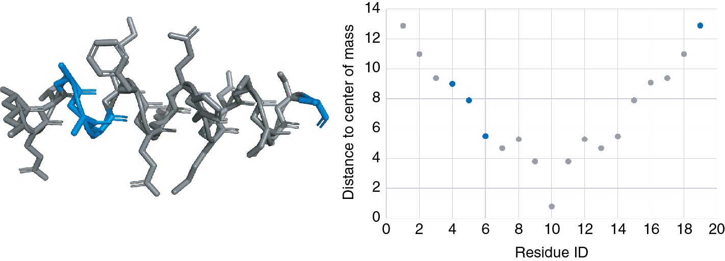
We have seen in the previous section that our interpretation engine is able to translate a list of vocalized keywords into an application command, but it provides further possibilities through its semantic-based architecture. Each interaction of the user with a structural group, a property, or an analytical value is ultimately translated into a list of individuals and their associated representations. This capability allows to not only execute commands within the dedicated software but also to synchronize the visual and analytical spaces between each other. As a consequence, each command that involved a selection is not only interpreted by the software but also by the platform that passes on the selection information to all spaces and their components (e.g., plots, graphs, etc.). (See Figure 5.)
Any selection made by the user triggers an event transmitted to a management module, resulting in an adaptation of the visualization to highlight the individual(s) selected.
|
Beyond its highlighting impact, a selection also reduces the user focus to a subset of individuals, both in the analysis space and the visualization one. It is possible to adapt this focus according to the user’s needs by modifying the context level at which they want their selection to appear. Three levels of contextualization are possible:
- No context – The selection of individual(s) leads to the unique visualization of these individuals in the visualization and analysis space and therefore hides any unselected individuals.
- Weak context – The selection of individual(s) highlights these individuals in the workspaces and reduces the perception of other individuals of the dataset (grey color, transparency, simplified visual rendering, etc.).
- Strong context – The selection of individual(s) is only perceived through a simple emphasis on these individuals in the work spaces. Any other individual will also appear with visual parameters close to the selected individuals.
These different levels make it possible either to highlight the differences between the selection and the rest of the data set, or to set up a streamlined working environment on a selection of interest to the user. These levels apply to both the visual and analytic parts through visual rendering systems specific to each space.
Semi-automated analyses triggered by direct interactions
Although the majority of the data is present in the database created by the user, a regular work session often requires additional data, for example resulting from post-simulation calculations and therefore missing from the original database. These calculations are usually managed within scripts, sometimes linked to simulation tools, and executed outside the visualization loop as a result of the observation of a particular phenomenon during the exploration or following other analyses already performed beforehand. In order not to overload the database and leave the user in control of the analyses he wants to perform, we have set up the possibility of launching some semi-automated analyses during the working session.
SPARQL query language allows, in addition to querying a database, to modify, delete, or add data to the database. This possibility allows to feed the database with the results of analyses launched during the working session of a user. A list of analyses has been compiled and an ontological definition has been defined for each of them. This definition provides the type of data used as input and the type of data output. Thus, with respect to the desired analysis, our platform will propose a filtered choice of individuals to be selected whose type match the data type expected. In the same way, the values generated as output of the analysis are automatically entered into the database with respect to their ontological definition.
A "distance" tool requires, for example, two individuals of the same hierarchical level, or a selection of individuals of higher hierarchical level, between which these distances will be calculated. It is possible to classify these analyses into two categories:
- Simple analyses group together analyses that generate a value that can be added directly to the properties of the individuals concerned. These include solvent accessibility, hydrophobicity, energy, and so on.
- Complex analyses are the result of a property describing a relationship between two individuals and thus requiring knowledge of these individuals to be perceptible. Complex analyses linking two individuals; the distance between two atoms, the RMSD between two sets of individuals, the angle between two chains, etc., are just some of the complex analyses that link two individuals.
While simple analyses simply add a property and the associated value to an individual, complex analyses must create a particular instance of one of the "analysis" concepts of the ontology. This concept will bring together the information/definition needed to understand it. For example, the ontology’s distance (analysis type) concept will store any calculated distance between two individuals for a selection of defined parent structures. The value of the distance, the URI of the two individuals involved, and all the structures within which the calculation was carried out will be properties of a distance instance and will be accessible only through that instance. The difference between a SPARQL query accessing values from a simple analysis and the SPARQL query accessing values from a complex analysis is illustrated below:
SELECT DISTINCT ?temp WHERE {my:MODEL_161 my:temperature ?temp}
SELECT DISTINCT ?distance WHERE {?indiv rdf:type my:Distance . ?indiv my:objectA my:RES_3622 . ?indiv my:objectB my:RES_3626 . ?indiv my:distance ?distance}
Platform architecture
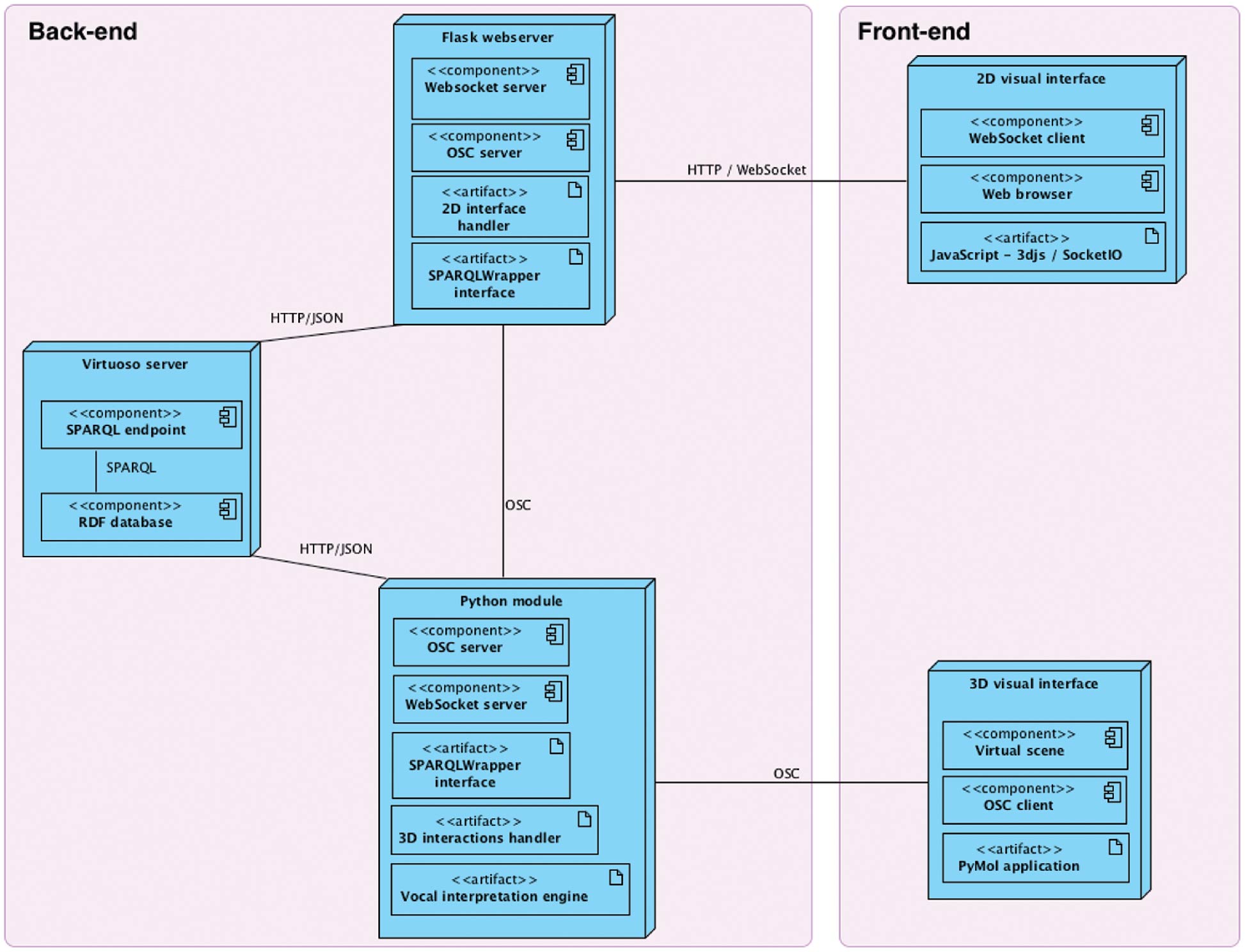
The different components highlighted in the previous sections must efficiently communicate with each other to provide realistic feedback to the users. Our platform architecture, both from a hardware and a software perspective, had to be carefully planned to ensure that all tasks performed by the users are treated within an interactive time-frame (on the order of magnitude of a second for the analyses). Our platform design is based on a complex software architecture. In the diagram shown in Figure 6, we deliberately placed it in the middle of a double-sided communication loop connecting the visualization space to the analysis space. Our database is hosted on a local server accessible from the network to guarantee privileged and optimized access to our data. All communications are optimized to reduce the latency between a request triggered by the front-end sensors, its translation into a query in the database together with the treatment and transformation of the query results in the back-end, and finally the response presented to the user, once again at the front-end level.
|
Scenario and evaluation
Scenario
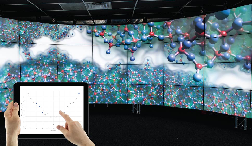
To illustrate the full-capacity of our platform architecture, we chose a typical example of a molecular system study. This example sets up a local visualization solution coupled to a distant web server where interactive graphs can be created. Both spaces can be rendered in an immersive environment, either in the same screen space or split on one 3D screen for the visualization and a tablet providing analysis results through a web server (see Figure 9, later). We assume, as it is the case in real studies, that the expert knows the molecular system well and can therefore interact vocally or by selecting elements in one of the spaces.
Our scenario studies the results of a molecular dynamics[31][32] experiment applied to a protein. We are voluntarily skipping the MD parametrization details since this was setup as a proof-of-concept and follows a very standard protocol.
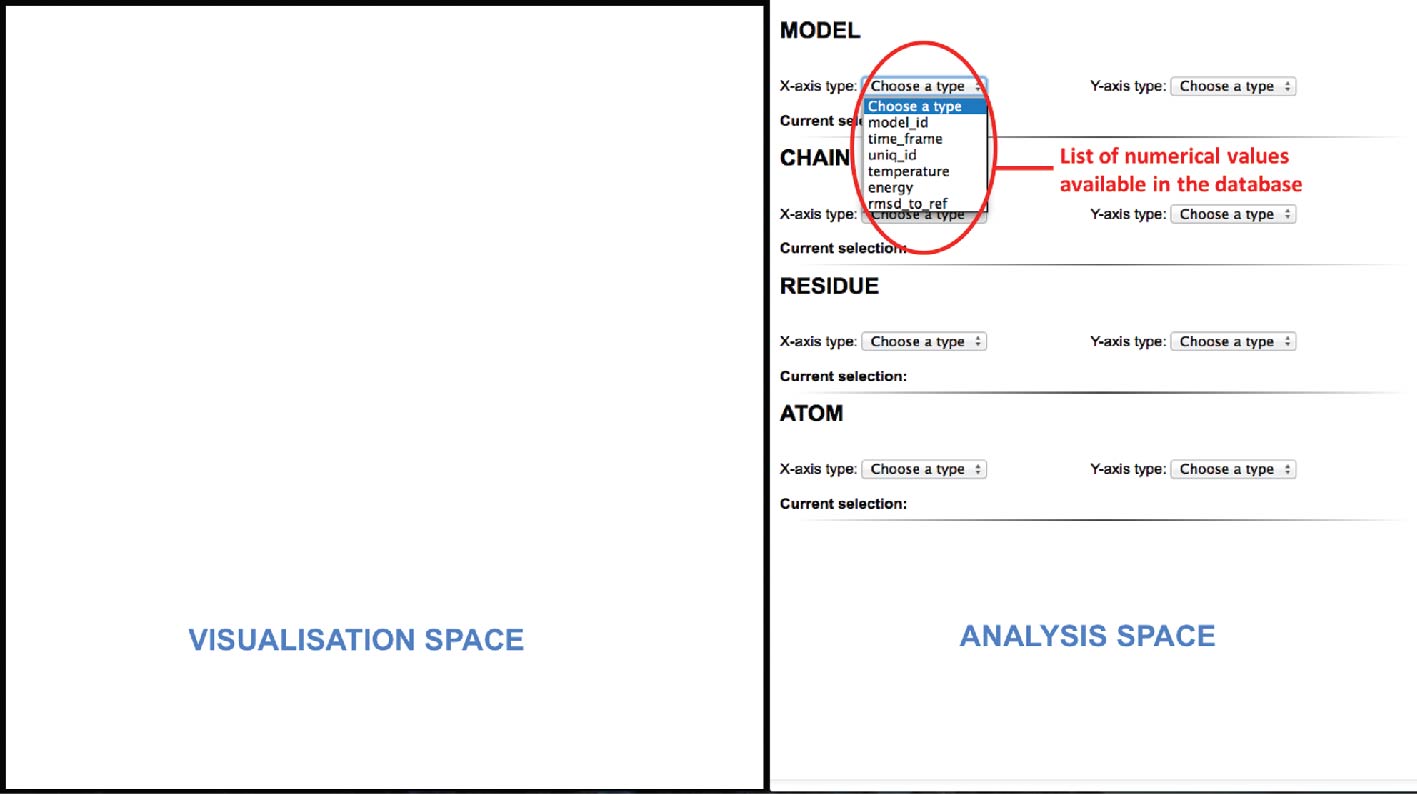
In the first step of our scenario, the analytical space (web server) triggers a SPARQL query to retrieve every numerical value from our database. A list containing all the values will then be created and presented to the user for each structural component level (Model/Chain/Residue/Atom) as illustrated in Figure 7. Once the data values are gathered, the expert will choose which structural component hierarchy he is interested in and which combination of properties he wants to plot in its analytical space.
|
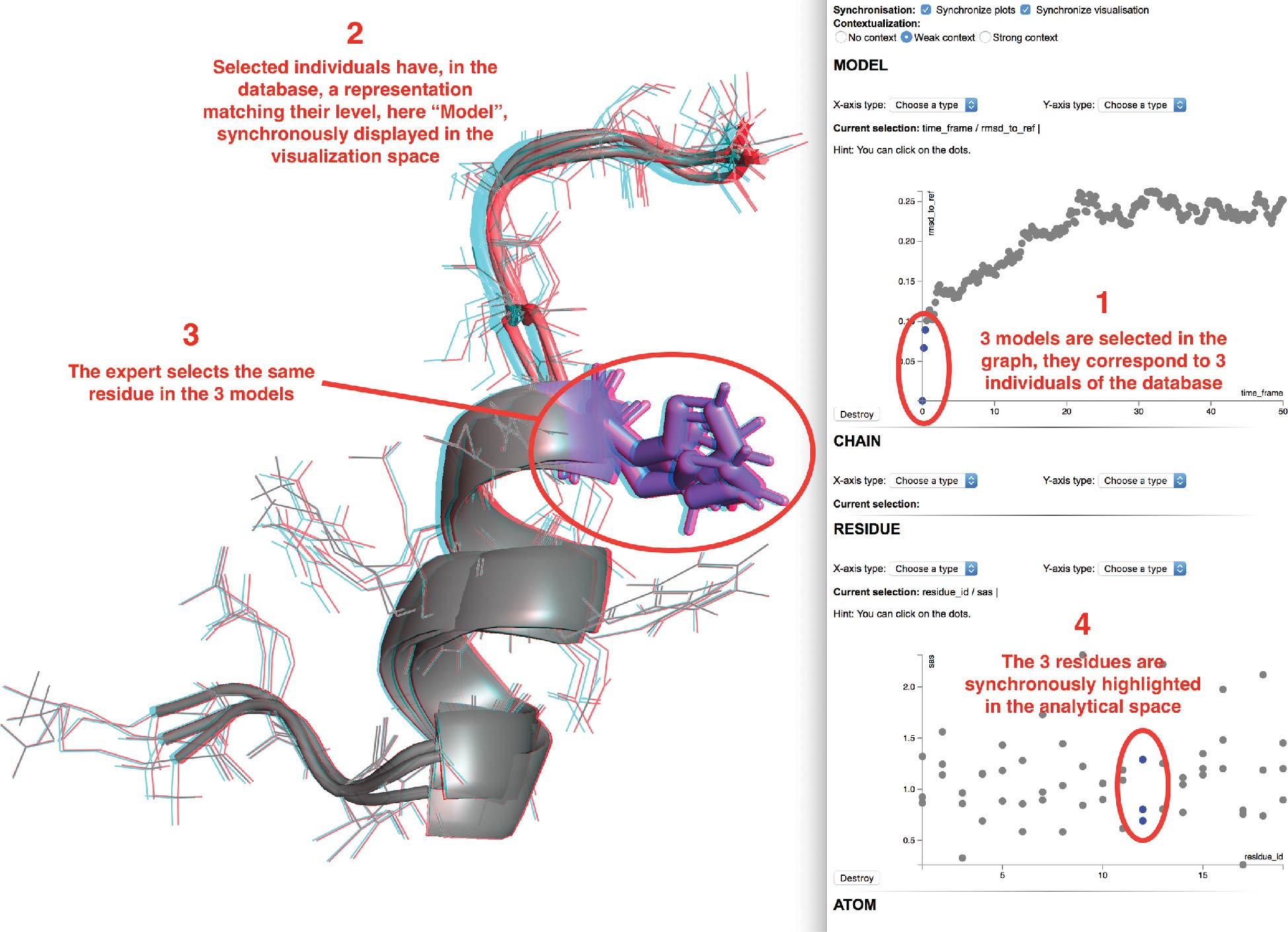
Several queries will retrieve the property values that will be plotted thanks to the graphs library D3.js. Here the RMSD of each model with respect to the starting conformation has been plotted. On the X-axis we see the time step corresponding to each model of the MD trajectory and on the Y-axis their associated RMSD value.
Several models of interest can be selected, either via a vocal command or by direct selection with the 2D interactive plots, as shown in the first step of Figure 8. We selected here the three lowest RMSD models (including the reference). The selection is synchronized over all previously created scatter plots and will trigger a synchronous visualization of the individuals in the visual space (see second step of Figure 8).
|
The expert may then switch to the visualization space and select some elements of the displayed structures he would like to focus on. We selected here three residues from the three different models. These sub-elements of the current models will be sent to the analytical space that will ask the expert for the properties to be plotted. As in the previous step, a list of available numerical values associated to the residues will be provided. Once the choice is made, the selection will be highlighted in the analytical space as shown in the third step of Figure 8. We chose here to display the solvent exposed area with respect to the residue IDs. In blue, the three residues we have selected in the visualization space are displayed as mentioned in the fourth step of Figure 8.
New graphs can be added at runtime and synchronized with the current ones. However, it is important to note that a full synchronization between the visualization and analytical spaces requires the same hierarchy of structural elements to be selected in both spaces. If a new selection is made at a model level, any graphs of lower hierarchy will be reset with the new selected models and the visualization will be reset with the new models at the same time.
Evaluation of high-level task completion based on hierarchical task analysis
The evaluation process started from the observation that the systematic evaluation of field-related tasks is rather complicated to set up for four reasons. (1) Usage and nature of the evaluated tools, in particular in molecular visualization, differ between experts. (2) Implementation and adaptation of our developments over a representative sample of the tools is complex and very time-consuming. (3) Our approach is biased since it is based on the execution of expert tasks. (4) In order to apply standard statistic methods for evaluation, it is necessary to gather enough participants, yet the number of experts in our application field is rather limited.
|
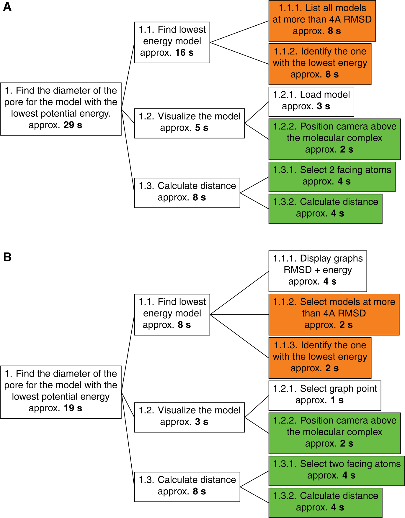
We therefore propose an evaluation method that is more theoretically oriented than empirical: the HTA method (for “Hierarchical Task Analysis”).[33] The HTA method consists of a division of a primary task into several sub-tasks. Each sub-task can be subdivided again until the sub-tasks reach a degree of precision sufficient to have their execution time evaluated accurately. This method is particularly useful to compare similar tasks performed under different conditions. It allows to evaluate both the task methodology with respect to specific conditions and the performance of the conditions for a specific task. HTA requires only one expert to compare the different sub-task execution times (see Figure 10).
|
We evaluate here a typical task that a structural biologist would perform on a daily basis. Here we asked experts to measure the diameter of the main pore of a transmembrane protein in two different setups. One is a typical setup where visualization software and some analysis files are available with an atomic model of the transmembrane protein. The second setup involves our platform, where the visualization software is now connected to a web page where interactive graphs can be displayed. The expert can interact with both spaces through two different devices connecting locally and where network latency is negligible. Tests have been made with a laptop where an instance of PyMol was running and a tablet where 2D plots were displayed within a web browser.
The task can be divided into three distinct steps. It requires a first step in the processing of analytical data where the lowest energy model will be sought among models more than 10 Å of RMSD distant from the reference model, this distance reflecting significant conformational changes. When the model concerned is identified, it should be visualized in order to see the pore and be able to select its ends. The third and final step consists of calculating the distance between two atoms on either side of the pore.
There is a significantly shorter runtime when using our platform (19 seconds) compared to a standard use of the analysis and visualization tools (29 seconds). The first step of analysis is the stage where the difference is most important and is highlighted by the orange sub-tags in the HTA graph in Figure 10. This difference can be explained by the use of interactive graphs to visualize RMSD and energy values for all models. The interactive graph and the selection tools associated (vocal recognition or manual selection) allow to quickly query all models more than 10 Å away from the reference. Identifying the model with the lowest energy is then a really quick visual analysis of the energy graph. On the opposite, use of standard tools in command-line is more complicated because it requires a more complex visual analysis. It is indeed more tedious to find a minimum value while going over a text file than by looking at a cloud of dots.
Then, the synchronization of the plot selections within the analytical space allows us to even further shorten the time required to find the lowest energy model in the second plot among the ones selected in the first.
Loading the model into the visualization software is also made easier in the platform since our application makes it possible to automatically pass on the selection of the model from a plot directly into the visualization space. The similar steps, shown in green in Figure 10, involve execution times and are therefore independent of the working conditions in which the sub-tasks are performed.
Conclusion
Immersive virtual reality is yet used only sparsely to explore biomolecules, which may be due to limitations imposed by several important constraints.
On the one hand, applications usable in virtual reality do not offer enough interaction modalities adapted to the immersive context to access the essential and usual features of molecular visualization software. In such a context, paradigms of direct interaction are lacking, both to make selections directly on the 3D representation of the molecule, and through complex criteria, to interactively change the different modes of molecular representations used to represent these selections. Until now, these selection tasks have to be made by the usual means like mouse and keyboard.
On the other hand, the impossibility of performing other analysis, pre- and post-processing tasks or visualizing these analysis results, closer to the field of information visualization rather than 3D visualization, forces the user to come back systematically to an office context.
To address these issues, we have set up a semantic layer over an immersive environment dedicated to the interactive visualization and analysis of molecular simulation data. This setup was achieved through the implementation of an ontology describing both structural biology and interaction concepts manipulated by the experts during a study process. As a result, we believe that our pipeline might be a solid base for immersive analytics studies applied to structural biology. In the same vein as projects by Chandler et al.[34][35] we successfully combine several immersive views over a particular phenomenon.
Our architecture, built around heterogeneous components, achieves to bring together visualization and analytical spaces thanks to a common ontology-driven module that maintains a perfect synchronization between the different representations of the same elements in the two spaces. One strength of the platform is its independence regarding the visualization technology used for both spaces. Combinations are numerous, from a CAVE system coupled to a tablet to a VR headset showcasing a room where each wall would display either a 3D structure or some analysis. Our semantic layer lies beneath the visualization technology used and only provides bridges between heterogeneous tools aiming at exploring molecular structures on one side and complex analyses on the other.
The knowledge provided by the ontology can also significantly improve the interactive capability of the platform by proposing contextualized analysis choices to the user, adapted to the types of elements in his current focus. All along the study process, a set of specific analyses, non redundant with the ones already performed, can be interactively chosen to populate the database. A simple definition of analyses in the ontology, adding input and output types, is sufficient to decide whether an analysis is pertinent or not for a precise selection, and whether the resulting values are already present in the database or not.
The reasoning capability of the ontology allowed us to develop an efficient interpretation engine that can transform a vocal command composed of keywords into an application command. This framework paves the way for a multimodal supervision tool that would use the high-level description of the manipulated elements, as well as the heterogeneous interaction natures, to merge inputs and create intelligent and complex commands in line with the work of M.E. Latoschik.[36][37] The RDF/RDFS/OWL model coupled to the SPARQL language allows to enunciate rules of inference, which is particularly important for the decision taking process in collaborative contexts. In these contexts, two users may trigger a multimodal command, in a conjoint way, that can be difficult to interpret without proper rules. An effort would then have to be made to integrate these rules in a future supervisor of the input modality, based on the semantic model, considering users as elements of modality in a multimodal interaction.
Our approach is a proof of concept application and is available as a GitHub repository, but it opens the way to a new generation of scientific tools. We illustrated our developments through the field of structural biology but it is worth to note that the generic nature of the semantic web allows to extend our developments to most scientific fields where a tight coupling between visualization and analyses is important. We especially target to integrate all the concepts described in this paper in new molecular visualization tools such as UnityMol[38], which allows a more comfortable code integration compared to classical molecular visualization application.
Acknowledgements
The authors wish to thank Xavier Martinez for UnityMol pictures courtesy. This work was supported in part by the French national agency research project Exaviz (ANR-11-MONU-0003) and by the “Initiative d’Excellence” program from the French State (grant “DYNAMO”, ANR-11-LABX-0011-01; equipment grants Digiscope, ANR-10-EQPX-0026 and Cacsice, ANR-11-EQPX-0008).
Conflict of interest
Authors state no conflict of interest. All authors have read the journal’s publication ethics and publication malpractice statement available at the journal’s website and hereby confirm that they comply with all its parts applicable to the present scientific work.
References
- ↑ Zhao, G.; Perilla, J.R.; Yufenyuy, E.L. et al. (2013). "Mature HIV-1 capsid structure by cryo-electron microscopy and all-atom molecular dynamics". Nature 497 (7451): 643–6. doi:10.1038/nature12162. PMC PMC3729984. PMID 23719463. https://www.ncbi.nlm.nih.gov/pmc/articles/PMC3729984.
- ↑ Zhang, J.; Ma, J.; Liu, D. et al. (2017). "Structure of phycobilisome from the red alga Griffithsia pacifica". Nature 551 (7678): 57–63. doi:10.1038/nature24278. PMID 29045394.
- ↑ van Dam, A.; Forsberg, A.S.; Laidlaw, D.H. et al. (2000). "Immersive VR for scientific visualization: A progress report". IEEE Computer Graphics and Applications 20 (6): 26–52. doi:10.1109/38.888006.
- ↑ Stone. J.E.; Kohlmeyer, A.; Vandivort, K.L.; Schulten, K. (2010). "Immersive molecular visualization and interactive modeling with commodity hardware". Proceedings of the 6th International Conference on Advances in Visual Computing: 382–93. doi:10.1007/978-3-642-17274-8_38.
- ↑ O'Donoghue, S.I.; Goodsell, D.S.; Frangakis, A.S. et al. (2010). "Visualization of macromolecular structures". Nature Methods 7 (3 Suppl.): S42–55. doi:10.1038/nmeth.1427. PMID 20195256.
- ↑ Hirst, J.D.; Glowacki, D.R.; Baaden, M. et al. (2014). "Molecular simulations and visualization: Introduction and overview". Faraday Discussions 169: 9–22. doi:10.1039/c4fd90024c. PMID 25285906.
- ↑ Goddard, T.D., Huang, C.C.; Meng, E.C. et al. (2018). "UCSF ChimeraX: Meeting modern challenges in visualization and analysis". Protein Science 27 (1): 14–25. doi:10.1002/pro.3235. PMC PMC5734306. PMID 28710774. https://www.ncbi.nlm.nih.gov/pmc/articles/PMC5734306.
- ↑ Férey, N.; Nelson, J.; Martin, C. et al. (2009). "Multisensory VR interaction for protein-docking in the CoRSAIRe project". Virtual Reality 13: 273. doi:10.1007/s10055-009-0136-z.
- ↑ 9.0 9.1 DeLano, W. (4 September 2000). "The PyMOL Molecular Graphics System". http://pymol.sourceforge.net/overview/index.htm.
- ↑ Humphrey, W.; Dalke, A.; Schulten, K. et al. (1996). "VMD: Visual molecular dynamics". Journal of Molecular Graphics 14 (1): 33–8. doi:10.1016/0263-7855(96)00018-5.
- ↑ Lv, Z.; Tek, A.; Da Silva, F. et al. (2013). "Game on, science - How video game technology may help biologists tackle visualization challenges". PLoS One 8 (3): e57990. doi:10.1371/journal.pone.0057990. PMC PMC3590297. PMID 23483961. https://www.ncbi.nlm.nih.gov/pmc/articles/PMC3590297.
- ↑ Sowa, J.F. (1984). Conceptual structures: Information processing in mind and machine. Addison-Wesley Longman Publishing Co. ISBN 0201144727.
- ↑ Berners-Lee, T.; Hendler, J.; Lassila, O. (2001). "The Semantic Web". Scientific American 284: 28–37.
- ↑ Cyganiak, R.; Wood, D.; Lanthaler, M., ed. (25 February 2014). "RDF 1.1 Concepts and Abstract Syntax". World Wide Web Consortium. https://www.w3.org/TR/rdf11-concepts/.
- ↑ Brickley, D.; Guha, R.V., ed. (25 February 2014). "RDF Schema 1.1". World Wide Web Consortium. https://www.w3.org/TR/rdf-schema/.
- ↑ Motik, B.; Patel-Schneider, P.F.; Parsia, B., ed. (11 December 2012). "OWL 2 Web Ontology Language". World Wide Web Consortium. https://www.w3.org/TR/owl2-syntax/.
- ↑ Harris, S.; Seaborne, A., ed. (21 March 2013). "SPARQL 1.1 Query Language". World Wide Web Consortium. https://www.w3.org/TR/sparql11-query/.
- ↑ De Giacomo, G.; Lenzerini, M. (1996). "TBox and ABox Reasoning in Expressive Description Logics". Proceedings of the Fifth International Conference on Principles of Knowledge Representation and Reasoning: 316–27. ISBN 1558604219.
- ↑ Schulze-Kremer, S. (2002). "Ontologies for molecular biology and bioinformatics". In Silico Biology 2 (3): 179–93. PMID 12542404.
- ↑ Schuurman, N.; Leszcynski, A. (2008). "Ontologies for bioinformatics". Bioinformatics and Biology Insights 2: 187—200. PMC PMC2735951. PMID 19812775. https://www.ncbi.nlm.nih.gov/pmc/articles/PMC2735951.
- ↑ The Gene Ontology Consortium, Ashburner, M.; Ball, C.A. et al. (2000). "Gene ontology: Tool for the unification of biology". Nature Genetics 25 (1): 25–9. doi:10.1038/75556. PMC PMC3037419. PMID 10802651. https://www.ncbi.nlm.nih.gov/pmc/articles/PMC3037419.
- ↑ Rabattu, P.Y.; Massé, B.; Ulliana, F. et al. (2015). "My Corporis Fabrica Embryo: An ontology-based 3D spatio-temporal modeling of human embryo development". Journal of Biomedical Semantics 6: 36. doi:10.1186/s13326-015-0034-0. PMC PMC4582726. PMID 26413258. https://www.ncbi.nlm.nih.gov/pmc/articles/PMC4582726.
- ↑ Smith, B.; Ashburner, M.; Rosse, C. et al. (2007). "The OBO Foundry: Coordinated evolution of ontologies to support biomedical data integration". Nature Biotechnology 25 (11): 1251–5. doi:10.1038/nbt1346. PMC PMC2814061. PMID 17989687. https://www.ncbi.nlm.nih.gov/pmc/articles/PMC2814061.
- ↑ Belleau, F.; Nolin, M.A;. Tourigny, N. et al. (2008). "Bio2RDF: towards a mashup to build bioinformatics knowledge systems". Journal of Biomedical Informatics 41 (5): 706–16. doi:10.1016/j.jbi.2008.03.004. PMID 18472304.
- ↑ Hanwell, M.D.; Curtis, D.E.; Lonie, D.C. et al. (2012). "Avogadro: An advanced semantic chemical editor, visualization, and analysis platform". Journal of Cheminformatics 4 (1): 17. doi:10.1186/1758-2946-4-17. PMC PMC3542060. PMID 22889332. https://www.ncbi.nlm.nih.gov/pmc/articles/PMC3542060.
- ↑ Rysavy, S.J.; Bromley, D.; Daggett, V. (2014). "DIVE: A Graph-Based Visual-Analytics Framework for Big Data". IEEE Computer Graphics and Applications 34 (2): 26–37. doi:10.1109/MCG.2014.27.
- ↑ Rzepa, H. (2012). "Chemical Markup Language". CMLC. http://www.xml-cml.org/.
- ↑ 28.0 28.1 Huang, X.; Alleva, F.; Hsiao-Wuen, H. et al. (1993). "The SPHINX-II speech recognition system: An overview". Computer Speech & Language 7 (2): 137–148. doi:10.1006/csla.1993.1007.
- ↑ Genest, D.; Salvat, E. (1998). "A platform allowing typed nested graphs: How CoGITo became CoGITaNT". Proceedings from the 1998 International Conference on Conceptual Structures: 1154–61. doi:10.1007/BFb0054912.
- ↑ Dennemont, Y. (2013). "Une assistance à l'interaction 3D en réalité virtuelle par un raisonnement sémantique et une conscience du contexte". Allen Institute for Artificial Intelligence. https://www.semanticscholar.org/paper/Une-assistance-%C3%A0-l'interaction-3D-en-r%C3%A9alit%C3%A9-par-un-Dennemont/254289782f5feb44e0a0db19ea2f7661578241a1.
- ↑ Abraham, M.J.; Murtola, T.; Schulz, R. et al. (2015). "GROMACS: High performance molecular simulations through multi-level parallelism from laptops to supercomputers". SoftwareX 1–2: 19–25. doi:10.1016/j.softx.2015.06.001.
- ↑ Dror, R.O.; Dirks, R.M.; Grossman, J.P. et al. (2012). "Biomolecular simulation: A computational microscope for molecular biology". Annual Review of Biophysics 41: 429–52. doi:10.1146/annurev-biophys-042910-155245. PMID 22577825.
- ↑ Annett, J. (2003). "Hierarchical Task Analysis". In Hollnagel, E.. Handbook of Cognitive Task Design. 1 (1st ed.). pp. 17–35. ISBN 9780805840032.
- ↑ Chandler, T.; Cordell, M.; Czaudema, T. et al. (2015). "Immersive Analytics". Proceedings of Big Data Visual Analytics 2015 1: 1–8. doi:10.1109/BDVA.2015.7314296.
- ↑ Sommer, B.; Barnes, D.G.; Boyd, S. et al. (2017). "3D-Stereoscopic Immersive Analytics Projects at Monash University and University of Konstanz". Proceedings of Electronic Imaging, Stereoscopic Displays and Applications XXVIII: 179–87, 189. doi:10.2352/ISSN.2470-1173.2017.5.SDA-109.
- ↑ Wiebusch, D.; Latoschik, M.E. (2015). "Decoupling the entity-component-system pattern using semantic traits for reusable realtime interactive systems". IEEE 8th Workshop on Software Engineering and Architectures for Realtime Interactive Systems: 25–32. doi:10.1109/SEARIS.2015.7854098.
- ↑ Gutierrez, M.; Vexo, F.; Thalmann, D. (2005). "Semantics-based representation of virtual environments". International Journal of Computer Applications in Technology 23 (2–4): 229–38. doi:10.1504/IJCAT.2005.006484.
- ↑ Doutreligne, S.; Cragnolimi, T.; Pasquali, S. et al. (2014). "UnityMol: Interactive scientific visualization for integrative biology". IEEE 4th Symposium on Large Data Analysis and Visualization: 109–10. doi:10.1109/LDAV.2014.7013213.
Notes
This presentation is faithful to the original, with only a few minor changes to presentation. Some grammar and punctuation was cleaned up to improve readability. In some cases important information was missing from the references, and that information was added. The original references after 27 were slightly out of order in the original; due to the way this wiki works, references are listed in the order they appear. The original shows a reference [33] for Perilla et al., but no inline citation for 33 exists anywhere in the text; it has been omitted for this version. Footnotes were turned into inline URLs. Figure 5 and 9 is shown in the original, but no reference was made to them in the text; a presumption was made where to put the inline reference for each figure for this version. Nothing else was changed in accordance with the NoDerivatives portion of the license.
