Journal:Construction of control charts to help in the stability and reliability of results in an accredited water quality control laboratory
| Full article title | Construction of control charts to help in the stability and reliability of results in an accredited water quality control laboratory |
|---|---|
| Journal | Sustainability |
| Author(s) | da Silva, Flávia M.O.; Silvério, Karina S.; Castanheira, Maria I.; Raposo, Mariana; Imaginário, Maria J.; Simões, Isabel; Almeida, Maria A. |
| Author affiliation(s) | Polytechnic Institute of Beja |
| Primary contact | Email: flavia dot silva at ipbeja dot pt |
| Editors | Kazak, J.K.; Sciavicco, G.; Kamińska, J.A. |
| Year published | 2022 |
| Volume and issue | 14(22) |
| Article # | 15392 |
| DOI | 10.3390/su142215392 |
| ISSN | 2071-1050 |
| Distribution license | Creative Commons Attribution 4.0 International |
| Website | https://www.mdpi.com/2071-1050/14/22/15392 |
| Download | https://www.mdpi.com/2071-1050/14/22/15392/pdf (PDF) |
|
|
This article contains rendered mathematical formulae. You may require the TeX All the Things plugin for Chrome or the Native MathML add-on and fonts for Firefox if they don't render properly for you. |
|
|
This article should be considered a work in progress and incomplete. Consider this article incomplete until this notice is removed. |
Abstract
Overall, laboratory water quality analysis must have stability in their results, especially in laboratories accredited by ISO/IEC 17025. Accredited parameters should be strictly reliable. Using control charts to ascertain divergences between results is thus very useful. The present work applied a methodology of analysis of results through control charts to accurately monitor the results for a wastewater treatment plant. The parameters analyzed were pH, biological oxygen demand for five days (BOD5), chemical oxygen demand (COD), total suspended solids (TSS), and total phosphorus (TP). The stability of the results was analyzed from the control charts and 30 analyses performed in the last 12 months. From the results, it was possible to observe whether the results were stable, according to the rehabilitation factor, which cannot exceed WN = 1.00, and the efficiency of removal of pollutants, which remained above 70% for all parameters. The method of determining the technological reliability and stability of the treatment station by use of control charts proves to be an efficient tool for detecting any instability in the results. As such, this method helps to monitor the results of such analyses more clearly and thus enables a rapid response to possible disturbances and maintains the quality of the analysis control, as well as determining the accreditation entities.
Keywords: water quality, control charts, reliability, wastewater treatment
Introduction
Quality management in accredited laboratories consists of a set of actions based on the international regulatory standard ISO/IEC 17025. Maintaining quality across lab operations is seen as fundamental to maintaining the suitability of the lab's services and products. Organizations are increasingly looking for improvement in their processes and procedures (P&P) and have tools contributing to the achievement of their goals. Implementing and improving statistical controls, continuous improvement, training, and participation reduce a process’s variability and consequently increases quality and productivity. Some tools even help to ensure quality control, including check sheets, histograms, and control charts. [1,2] As Samohyl [3] notes, mindfully implementing these and other tools further ensures quality by minimizing variations in the characteristics of products and procedures.
A control chart—and charting in general—is of the main statistical tools used to control and monitor processes. Control charts signal the presence of accidental causes and special causes in a process. [4] According to Corrêa [5], every process has variation, and a natural or common cause is within the control limits. In contrast, so-called special causes need more attention because they indicate values outside the control limits and therefore need rapid correction. Using control charts to manage routine analyses allows easy detection of negative trends in analytical work, enabling quick corrective action, reducing out-of-specification (OOS) results, and consequently avoiding non-compliance. [6] They can be applied in several areas and are used worldwide. A study carried out by Razif [7] proves that the use of control charts contributed to faster detection of anomalies in a daily cycle of analysis and showed similarities in the characteristics of the water quality data of the Surabaya river in Indonesia between 2014 and 2015 for several parameters such as biological oxygen demand for five days (BOD5), chemical oxygen demand (COD), total suspended solids (TSS).
In an analogous study in Brazil using control charts in conjunction with other statistical tools, it was possible to identify a problem in the domestic sewage treatment plant. The treatment did not produce an effluent with characteristics that meet the specifications or release standards of the environmental legislation, indicating the need for restructuring and correction of the efficiency of the process. [8]
The international standard ISO 7870-1:2019 Control charts — Part 1: General guidelines addresses several objectives regarding control charts, including [1]:
- indicating if the process is stable, comparing information from samples that represent the current state of the process against the control limits that reflect this variability;
- estimating the magnitude of the variability inherent to the process; and
- aiming to determine if the variability of the process has remained stable or if there are oscillations.
A 2022 study by Liz and Piotr [9] concluded that control charts could be an effective tool for assessing the operation of a sewage treatment plant, allowing the detection of any disturbances during the sewage treatment process in the tested facility and the rapid correction of those disturbances, ensuring the natural reservoir’s water quality. The Shewhart-type control chart is the most used and has broad applicability. In building this model, a preliminary period of subsequent sample analysis is needed to determine the control limits. [10] After this analysis period, statistical treatment is applied to obtain the control charts.
According to Zan et al. [11], control charts are used to monitor whether a process is controlled or not. They have long been used for quality monitoring of manufacturing processes. If only random causes affect the operation, the production process is considered to be natural or normal. [12] At this time, the control chart tends to fluctuate randomly in the symmetrical coordinate system. The traditional control chart easily detects the abnormity beyond the boundary. Still, it is challenging to identify the range of abnormity given that it usually requires human judgment and is easily affected by various factors.
The problem of water pollution in urban areas is highly relevant today due to progressive urbanization, aging of ecological infrastructure, and high population density. [9,13] The Member States of the European Union, in agreement with the Water Framework Directive (WFD), are obliged to use and protect their water resources rationally. These include the proper treatment of wastewater.
This study aims to apply a methodology of analysis of results through control charts, aiming at accurately monitoring the results for a wastewater treatment plant from a slaughterhouse in a specific region of Alentejo in Portugal. The parameters analyzed were pH, BOD5, COD, TSS, and total phosphorus (TP).
According to Reilly et al. [14], slaughterhouse wastewater presents a biological risk to humans and other animals due to the presence of pathogens, pharmaceuticals, and toxic chemicals used for plant cleaning. [15] This harmful potential means that the disposal of slaughterhouse and dairy waste is often subject to local legislation which has been put in place to protect public health. [16] For example, COD in slaughterhouse wastewater often requires a 95% reduction, with similar levels of treatment being required for TP before final discharge into the environment. [15] Currently, the UK dairy processing and slaughterhouse industries use technologies such as chemical dosing, reverse osmosis, anaerobic digestion, dissolved air floatation, and membrane bioreactors to treat their wastewater. They have been obtaining good results. [17,18,19]
This study will show the construction of control charts helps guide analysts when there are results outside the control lines, making it possible to reassess the results faster if necessary. Going forward, this method will assist laboratories in managing the quality of the results of their water and wastewater analysis.
Materials and methods
Description of the study
The School of Agriculture of the Polytechnic Institute of Beja has a water quality control laboratory accredited to ISO/IEC 17025, where water quality is analyzed. This laboratory is located in Beja, Portugal. The technological process of the wastewater treatment plant analyzed includes mechanical, biological, and chemical treatment of wastewater. The values of pollution indicators for sewage discharged into the municipality to the slaughterhouse may not exceed the following values: pH 19, BOD5 500.0 mg O2·L−1, COD 1500.0 mg O2·L−1, TSS 1000.0 mg·L−1, and TP 25 mg P·L−1. These values are accorded between the company and the municipality.
The objective was thus to create control charts for the pH, BOD5, COD, TSS, and TP parameters in analyzing a wastewater treatment plant from a slaughterhouse in Alentejo for 18 months (2021–2022).
Methods
The methodology was made according to Figure 1. The laboratory receives the wastewater samples, analyzes them, and creates a database with the data. The work was applied from this step forward, where the data was analyzed, and the control charts were created.
|
The creation of the control charts is structured with an upper control line (UCL), a lower control line (LCL), the process means or target (CL), and the observed points. This statistical tool shows the evolution over time of a characteristic, allowing the identification of the purpose of variations and assisting in a continuous improvement of the process to produce itself according to the specifications, keeping the process under statistical control. Statistical control is ensured through the lines of the control limits that allow real-time analysis of the progress of the process. This represents the statistic related to the variable of interest in case one or more points exceed the control limits, indicating that the process has a problem. [20]
For pollution indicators in treated sewage, control charts were within the boundaries of the helplines, and the control lines and the center line were determined considering the tree-sigma rule for the normal distribution N (μ, σ), where μ = average of the analyzed values, and σ = standard deviation of the analyzed variable. [9,21,22] Formulas were:
- Lower control line (LCL): LCL = μ − 3σ
- Lower warning line (LWL): LWL = μ − 2σ
- Lower helpline (LHL): LHL = μ − 1σ
- Center line (CL): CL = μ
- Upper helpline (UHL): UHL = μ + 1σ
- Upper warning line (UWL): UWL = μ + 2σ
- Upper control line (UCL): UCL = μ + 3σ
To analyze the technological reliability and stability of the wastewater treatment station in Alentejo, Portugal, with the use of control charts, some specifics were necessary. The coefficient of technical reliability was used, as with Śliz and Bugajski [9]:
where WN = plant reliability factor [−], xsr = average value of the analyzed pollution index in treated sewage [mg·dm−3], and xdop = permissible value of the analyzed pollution index in treated sewage [mg·dm−3].
The effectiveness of wastewater treatment was calculated according to the following formula:
where: ƞ = reduction of a particular pollutant index in treated sewage [%], Ss = value of the pollution index in raw sewage [mg·dm−3], and S0 = value of the pollution index in treated sewage [mg·dm−3].
To verify interruption or instability of the effluent treatment process from control charts, we can use the following parameters, as with Andraka [23]: eight consecutive points on one side of the central line, one point outside the control limits, two of the three points outside the ±2σ warning lines, and four of five consecutive points beyond the ±1σ extension lines. [9]
Control charts have three fundamental objectives: reducing variability, monitoring, and estimating process quality parameters. [24] In constructing control charts, it is essential and valuable to distinguish the two phases of implementation and construction.
In phase 1, a set of process data is analyzed retrospectively to understand the variation of the process over time, evaluate the stability of the process, and model the performance of the process under control. This last step is usually carried out by estimating the parametric model in phase 2, in which the process has been previously estimated. Phase 1 thus corresponds to a retrospective check of the process where the experimental control limits are calculated, while phase 2 is concerned with monitoring the process itself. [25]
Phase 2 begins after collecting a set of process data under stable conditions and is representative of the performance of the process under control. In phase 2, a control chart is used to monitor the process, comparing the sample statistics for each successive sample as extracted from the process with the control limits. [26]
Results
The results show the control charts for the inlet and outlet effluents of an existing wastewater treatment plant in a slaughterhouse in Alentejo, Portugal.
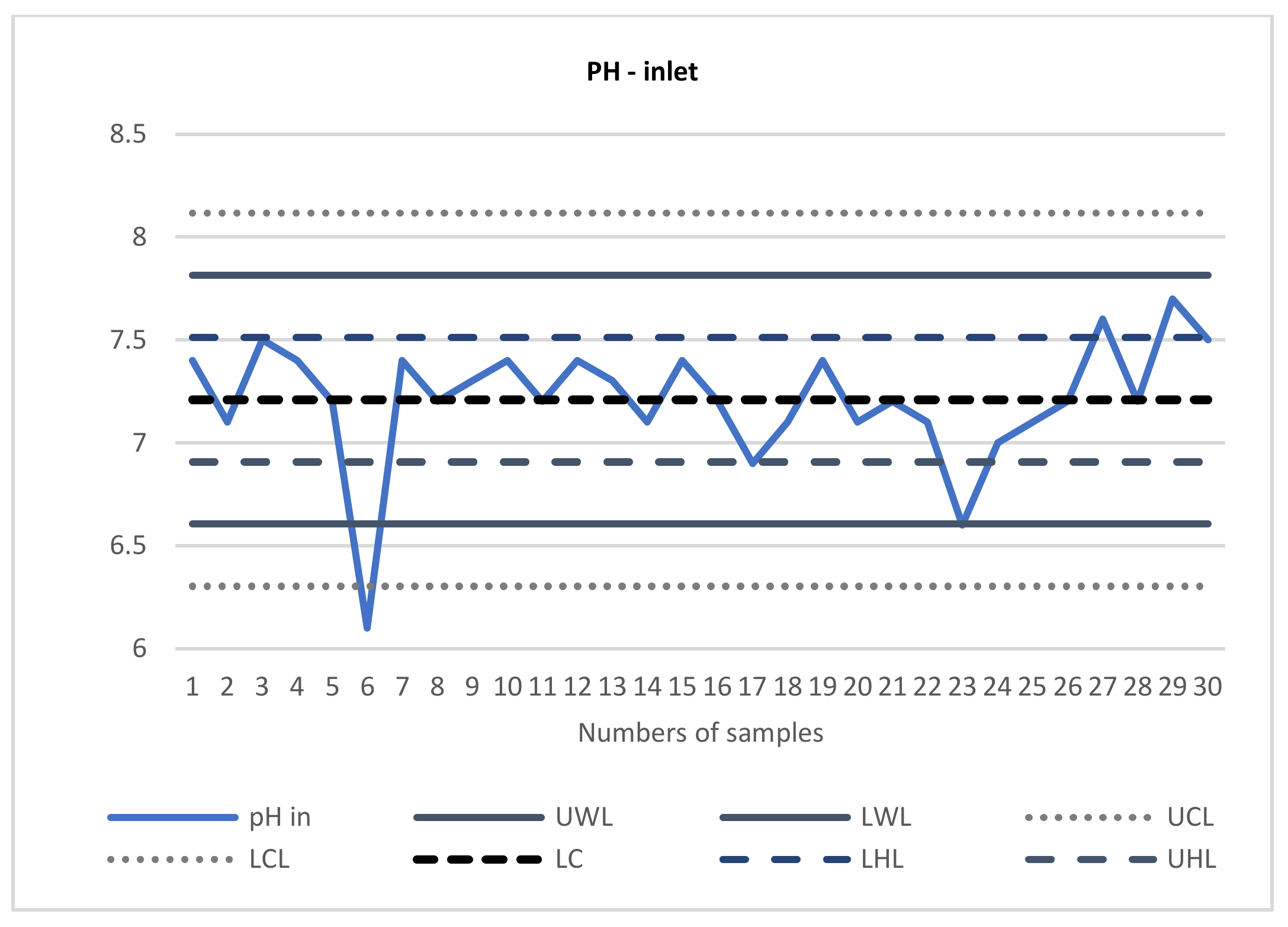
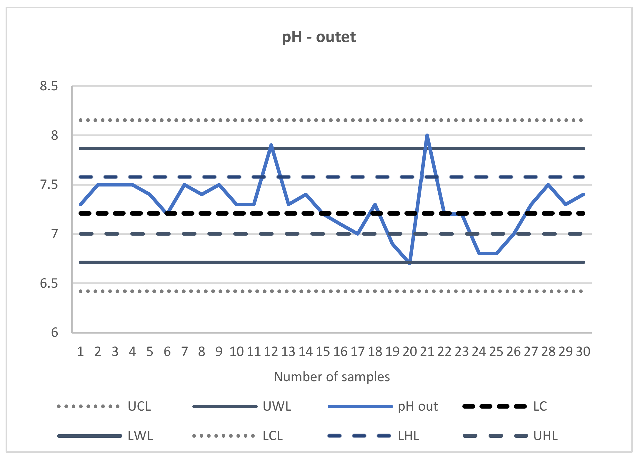
Figure 2 and Figure 3 show the inlet and outlet effluent behavior for the pH parameter. The control charts show the variation during the 30 days of treatment for wastewater.
|
|
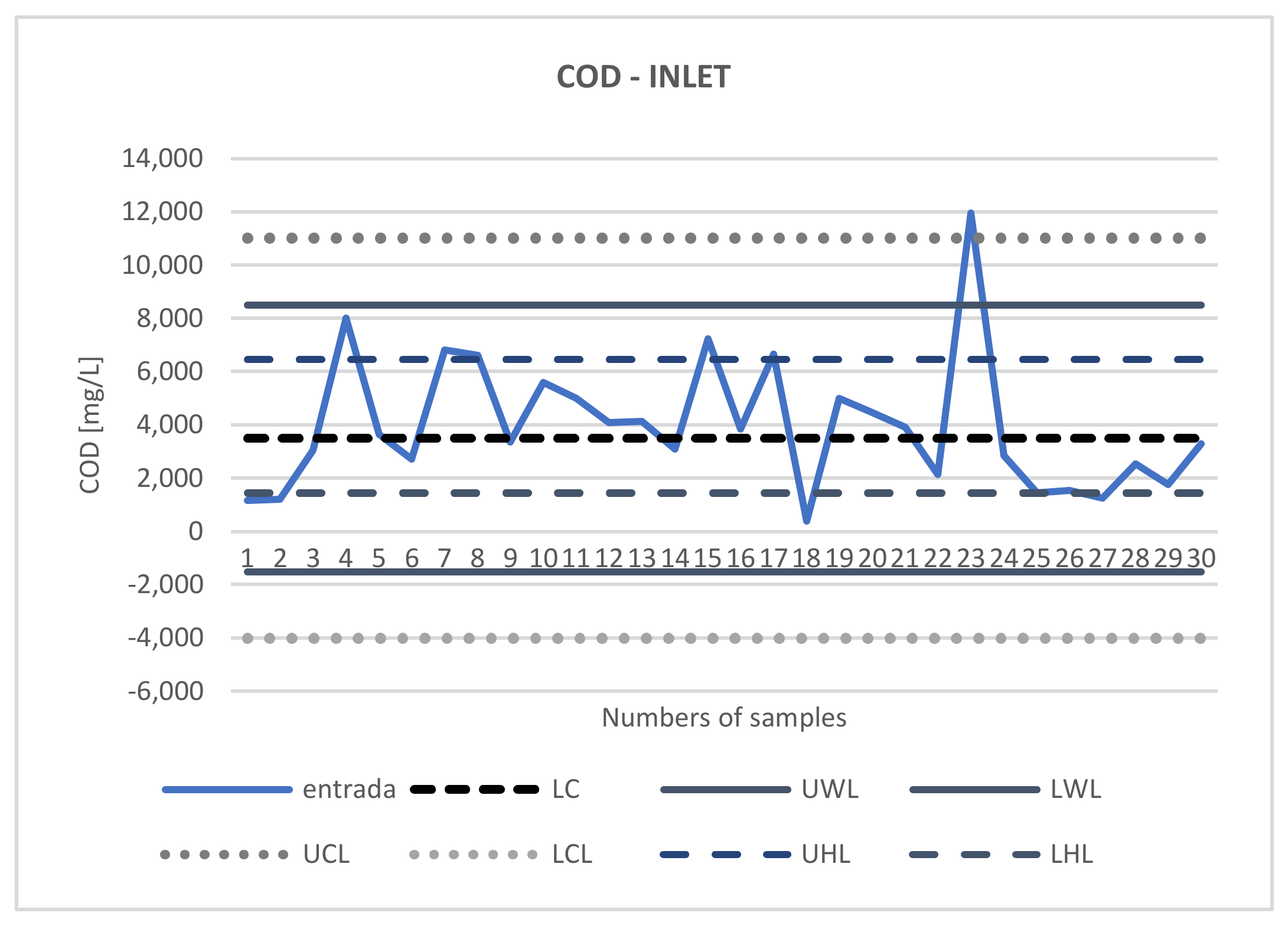
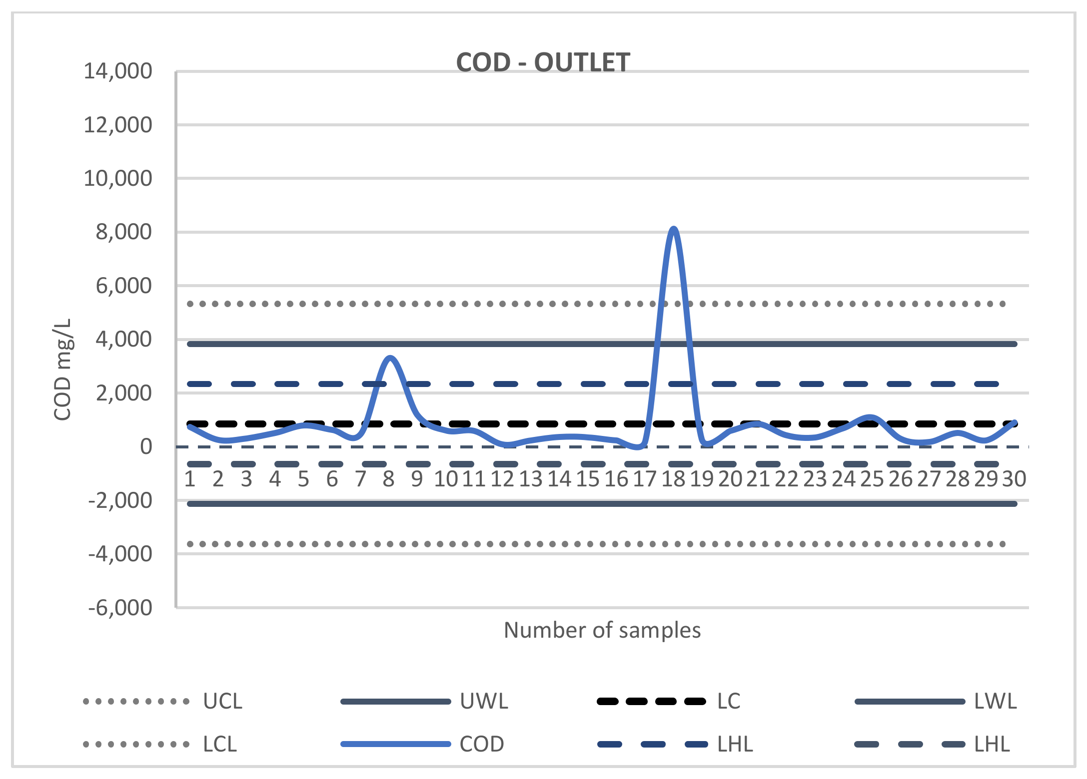
It can be seen that after treatment, the results are stabilized; this is the possible interpretation of the analysis definition of the control lines. Figure 4 shows the COD inlet results; compared to Figure 5, the COD outlet shows an improved system. For Figure 5, there is a first point close to the LWL, but it is not necessary to take control because the next point is far away from the LWL. Only two points cross the control lines, and this behavior does not jeopardize the treatment outcome.
|
|
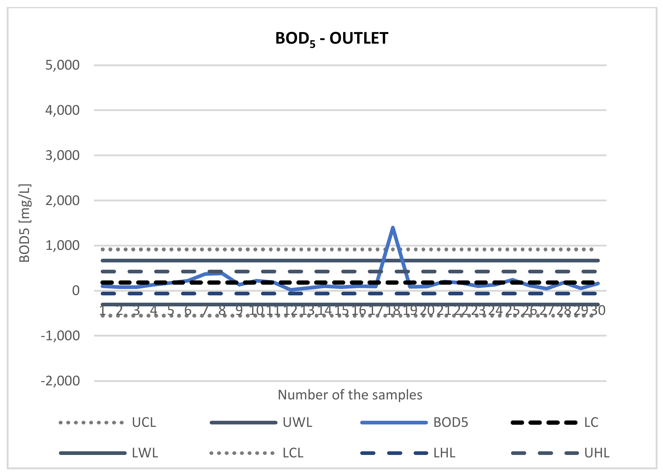
Analyzing the results for Figure 6 and Figure 7, it is possible to see the same stability of the results at the outlet of the treated effluent, with only one point crossing the UCL control line. Due to all the results obtained having this same point outside the standard, it is believed that the treatment was ineffective on this day.
|
|
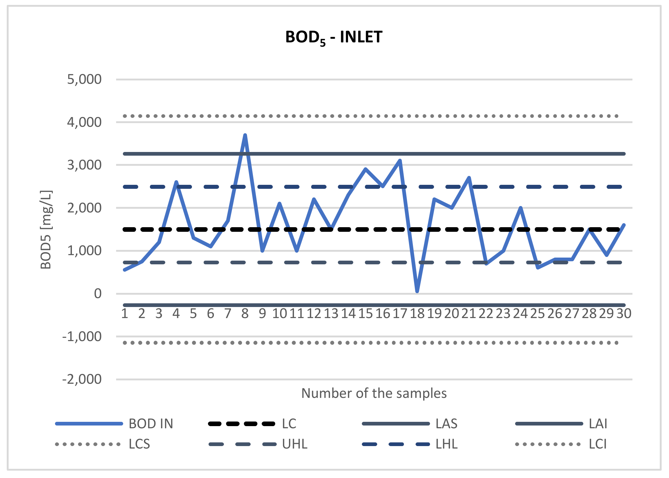
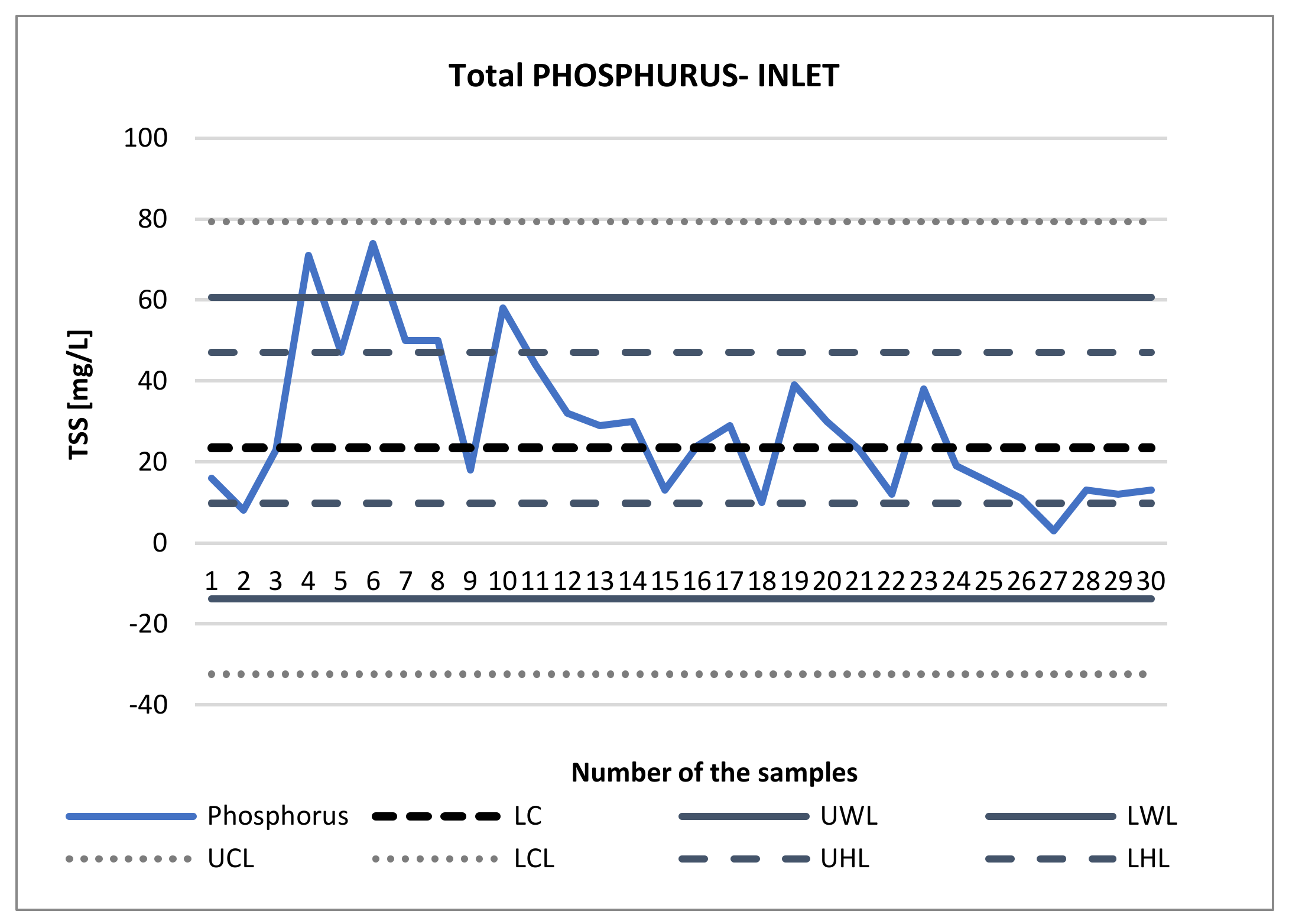
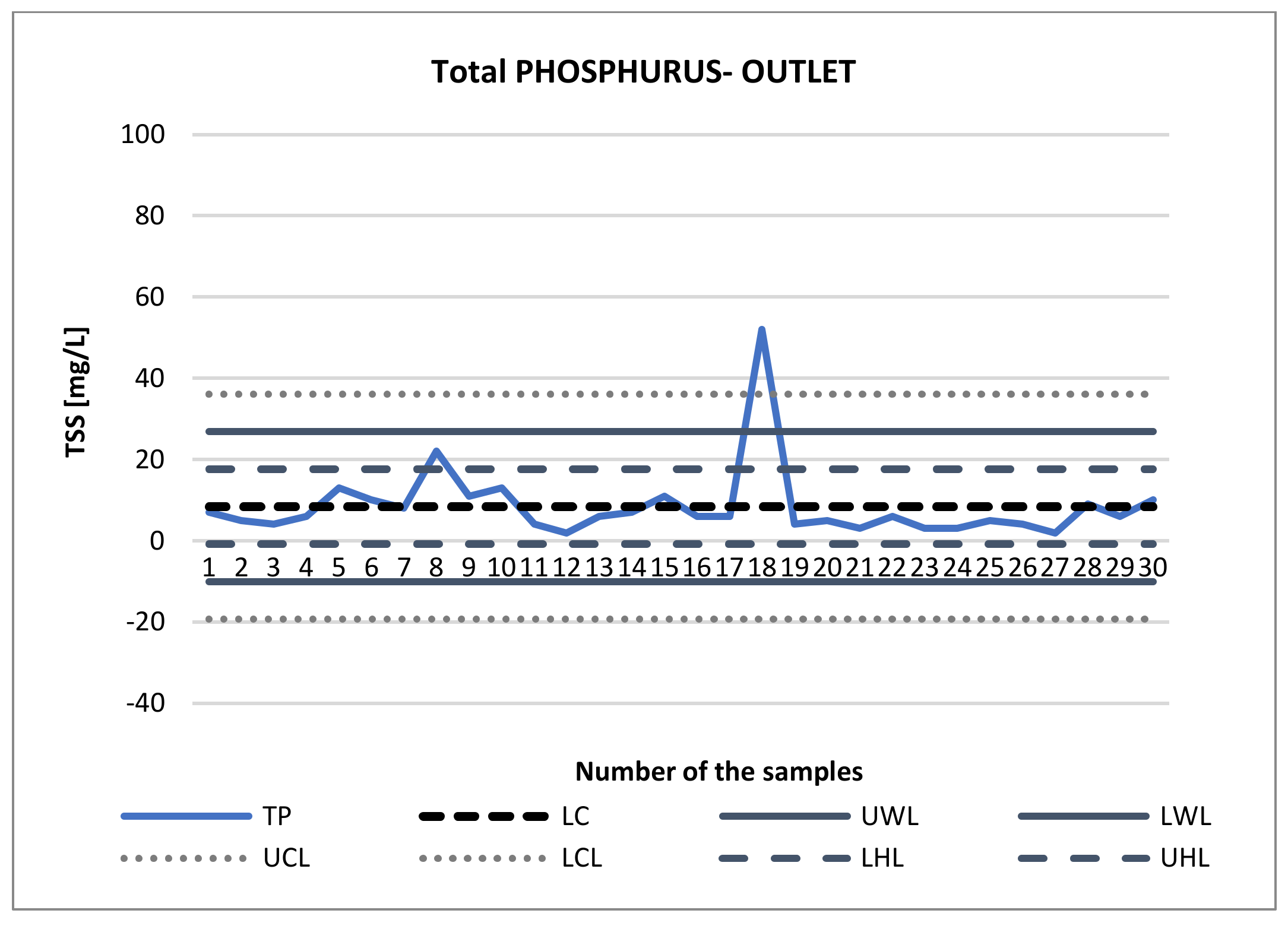
For total phosphorus results, Figure 8 and Figure 9 show similar results. The resulting line remains stable and only crosses the UHL line once; the results stay close to the LC control line across all samples.
|
|
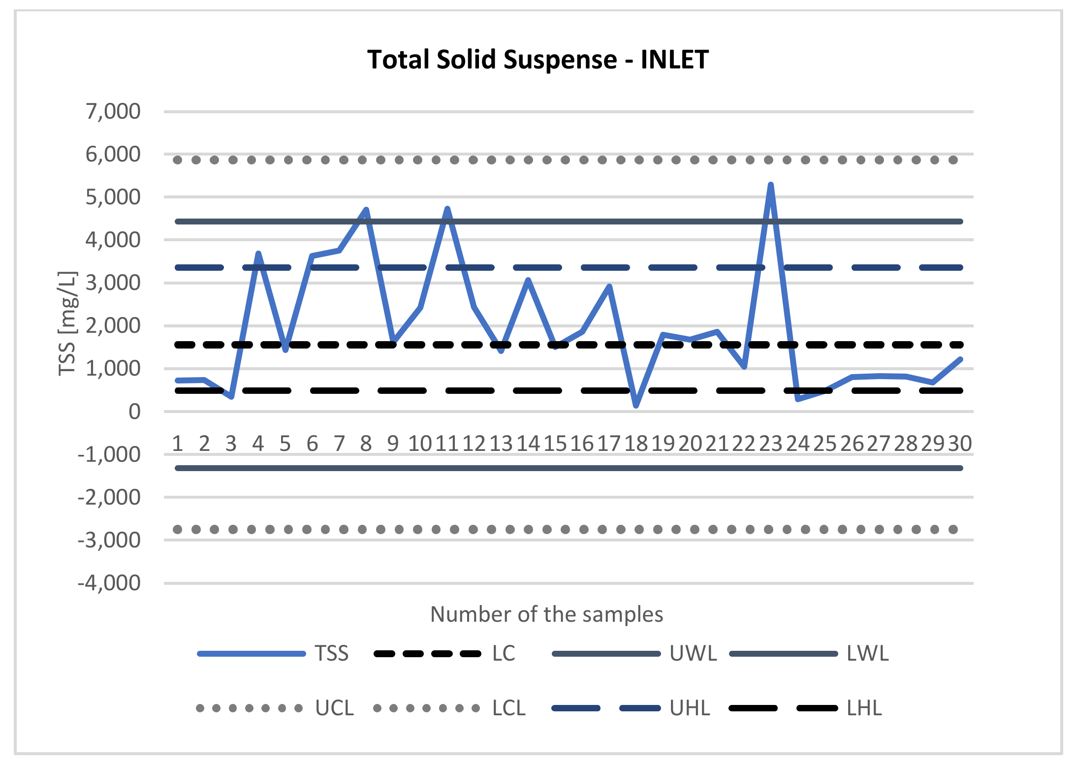
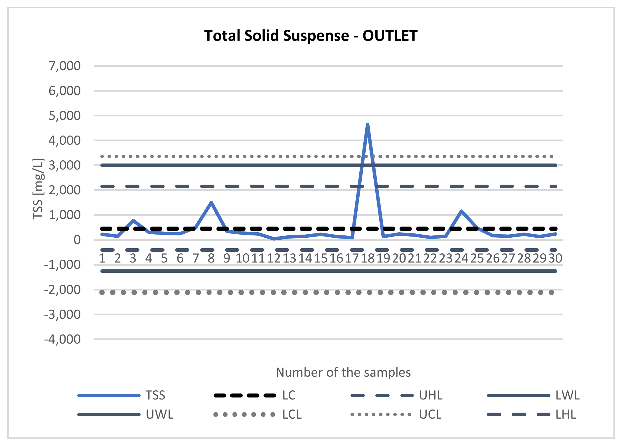
For the TSS inlet chart (Figure 10 and Figure 11) one sample exceeds the UWL line, and when observing the TSS outlet chart, it can be noted that the post-treatment results are stable, except on three occasions. In this situation, it may alert the company to a possible problem in the treatment in that specific period.
|
|
All control charts obtained were analyzed, and most points were under statistical control in Figures 2–11. In accordance with Montgomery [26], only rule 1, the presence of special causes of variation, was evaluated, and there was only one particular cause. With the process under statistical control in phase 1, it passes to phase 2, which consists of monitoring the process.
Note that the purpose of using the rules is to increase the sensitivity of control charts. However, care must be taken when using a set of rules, as an excessive number of false alarms may occur. The higher the number of rules to be used, the greater the number of false alarms. [26]
Table 1 shows the technological reliability coefficient against the average efficiency of the analyzed pollutant removal in the sewage treatment plant. It can be seen that the efficiency of reduction from treatment is good enough to reach more than 70% in all parameters analyzed, with better results for the BOD5 indicator, reaching 89%.
| ||||||||||||||||||||
The BOD5 parameter showed the lowest rehabilitation coefficient (WN) of 0.37 and, consequently, the most excellent technological reliability, which indicates a highly satisfactory result for this parameter. For COD and TSS parameters, the rehabilitation coefficient showed results of 0.57 and 0.45, respectively, indicating values that can be considered reasonably good. In the case of TP, the indicated value is within the legislation in force. However, it is the highest value for the rehabilitation coefficient and consequently has the lowest treatment efficiency among the analyzed parameters since the indicators are inversely proportional. A study by Mlyński [27] used the indicator to prove the technological reliability of the treatment plant, where it obtained results below 1.00. However, this was slightly higher when compared to the results obtained in the present study.
Discussion
References
Notes
This presentation is faithful to the original, with only a few minor changes to presentation. Grammar was tweaked significantly to improve readability. The PMCID and DOI were also added when they were missing from the original reference.


