Journal:From the desktop to the grid: Scalable bioinformatics via workflow conversion
| Full article title | From the desktop to the grid: Scalable bioinformatics via workflow conversion |
|---|---|
| Journal | BMC Bioinformatics |
| Author(s) | de la Garza, Luis; Veit, Johannes; Szolek, Andras; Röttig, Marc; Aiche, Stephan; Gesing, Sandra; Reinert, Knut; Kohlbacher, Oliver |
| Author affiliation(s) | University of Tübingen, Freie Universität Berlin, University of Notre Dame |
| Primary contact | Email: delagarza [at] informatik [dot] uni-tuebingen [dot] de |
| Year published | 2016 |
| Volume and issue | 17 |
| Page(s) | 127 |
| DOI | 10.1186/s12859-016-0978-9 |
| ISSN | 1471-2105 |
| Distribution license | Creative Commons Attribution 4.0 International |
| Website | https://bmcbioinformatics.biomedcentral.com/articles/10.1186/s12859-016-0978-9 |
| Download | https://bmcbioinformatics.biomedcentral.com/track/pdf/10.1186/s12859-016-0978-9 (PDF) |
|
|
This article should not be considered complete until this message box has been removed. This is a work in progress. |
Abstract
Background
Reproducibility is one of the tenets of the scientific method. Scientific experiments often comprise complex data flows, selection of adequate parameters, and analysis and visualization of intermediate and end results. Breaking down the complexity of such experiments into the joint collaboration of small, repeatable, well defined tasks, each with well defined inputs, parameters, and outputs, offers the immediate benefit of identifying bottlenecks, pinpoint sections which could benefit from parallelization, among others. Workflows rest upon the notion of splitting complex work into the joint effort of several manageable tasks.
There are several engines that give users the ability to design and execute workflows. Each engine was created to address certain problems of a specific community, therefore each one has its advantages and shortcomings. Furthermore, not all features of all workflow engines are royalty-free — an aspect that could potentially drive away members of the scientific community.
Results
We have developed a set of tools that enables the scientific community to benefit from workflow interoperability. We developed a platform-free structured representation of parameters, inputs, outputs of command-line tools in so-called Common Tool Descriptor documents. We have also overcome the shortcomings and combined the features of two royalty-free workflow engines with a substantial user community: the Konstanz Information Miner, an engine which we see as a formidable workflow editor, and the Grid and User Support Environment, a web-based framework able to interact with several high-performance computing resources. We have thus created a free and highly accessible way to design workflows on a desktop computer and execute them on high-performance computing resources.
Conclusions
Our work will not only reduce time spent on designing scientific workflows, but also make executing workflows on remote high-performance computing resources more accessible to technically inexperienced users. We strongly believe that our efforts not only decrease the turnaround time to obtain scientific results but also have a positive impact on reproducibility, thus elevating the quality of obtained scientific results.
Keywords
Workflow, interoperability, KNIME, grid, cloud, Galaxy, gUSE
Background
The importance of reproducibility for the scientific community has been a topic lately discussed in both high-impact scientific publications and popular news outlets.[1][2] To be able to independently replicate results — be it for verification purposes or to further advance research — is important for the scientific community. Therefore, it is crucial to structure an experiment in such a way that reproducibility could be easily achieved.
Workflows are structured, abstract recipes that help users construct a series of steps in an organized way. Each step is a parametrised specific action that receives some input and produces some output. The collective execution of these steps is seen as a domain-specific task.
With the availability of biological big data, the need to represent workflows in computing languages has also increased.[3] Scientific tasks such as genome comparison, mass spectrometry analysis, protein-protein interaction, just to name a few, access extensive datasets. Currently, a vast number of workflow engines exist[4][5][6][7][8], and each of these technologies has amassed a considerable user base. These engines support, in some way or another, the execution of workflows on distributed high-performance computing (HPC) resources (e.g., grids, clusters, clouds, etc.), thus allowing speedier obtention of results. A wise selection of a workflow engine will shorten the time spent between workflow design and retrieval of results.
Workflow engines
Galaxy[6] is a free web-based workflow system with several pre-installed tools for data-intensive biomedical research. Inclusion of arbitrary tools is reduced to the trivial task of creating ToolConfig[9] files, which are Extensible Markup Language documents (XML). The Galaxy project also features a so-called toolshed[10], from which tools can be obtained and installed on Galaxy instances. At the time of writing Galaxy’s toolshed featured 3470 tools. However, we have found that Galaxy lacks extended support for popular workload managers and middlewares.
Taverna[7] offers an open-source and domain-independent suite of tools used to design and execute scientific workflows, helping users to automate and pipeline processing of data coming from different web services. At the time of writing Taverna features more than 3500 services available on startup and it also provides access to local and remote tools. Taverna allows users to track results and data flows with great granularity, since it implements the Open Provenance Model standard (OPM).[11] A very attractive feature of Taverna is the ability to share workflows via the myExperiment research environment.[12]
The Konstanz Information Miner Analytics Platform (KNIME Analytics Platform)[4][13] is a royalty-free engine that allows users to build and execute workflows using a powerful and user-friendly interface. The KNIME Analytics Platform comes preloaded with several ready-to-use tasks (called KNIME nodes) that serve as the building stones of a workflow. It is also possible to extend the KNIME Analytics Platform by either downloading community nodes or building custom nodes using a well-documented process.[14][15] Workflows executed on the KNIME Analytics Platform are limited to run on the same personal computer on which it has been installed, thus rendering it unsuitable for tasks with high-memory or high-performance requirements. KNIME is offered in two variants able to execute workflows on distributed HPC resources: KNIME Cluster Execution[16], and KNIME Server.[17] These two suites are, however, royalty-based — an aspect that might shy away users of the scientific community.
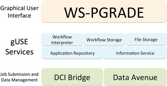
The grid and cloud User Support Environment (gUSE) offers an open-source, free, web-based workflow platform able to tap into distributed HPC infrastructures.[5] gUSE entails a set of components and services that offers access to distributed computing interfaces (DCI). The Web Services Parallel Grid Runtime and Developer Environment Portal (WS-PGRADE) component acts as the graphical user interface. This web-based portal is a series of dynamically generated web pages, through which users can create, execute, and monitor workflows. WS-PGRADE communicates with internal gUSE services (e.g., Workflow Interpreter, Workflow Storage, Information Service) using the Web Services Description Language (WSDL).[18] Passing documents in the WSDL format between its components allows gUSE services to interact with other workflow systems. Figure 1 shows the three-tiered architecture of gUSE. This complex and granular architecture of gUSE enables administrators to distribute the installation of gUSE across resources. A typical set-up is to install WS-PGRADE on a dedicated web server, while installing other services and components on more powerful computers.
|
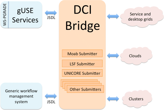
In order to provide a common workflow submission Application Programming Interface (API), gUSE channels workflow-related requests (i.e., start, monitor, cancel a job on a DCI) through the DCI Bridge component.[20] The DCI Bridge is fully compatible with the Job Submission Description Language (JSDL)[21], thus enabling other workflow management systems to interact with it in order to benefit from gUSE’s flexibility and DCI support. The DCI Bridge contains so-called DCI Submitters, each containing specific code to submit, monitor, cancel jobs on each of the supported DCIs (e.g., UNICORE[22], LSF[23], Moab[24]). Figure 2 presents a schematic overview of the interaction between the DCI Bridge and other components.
|
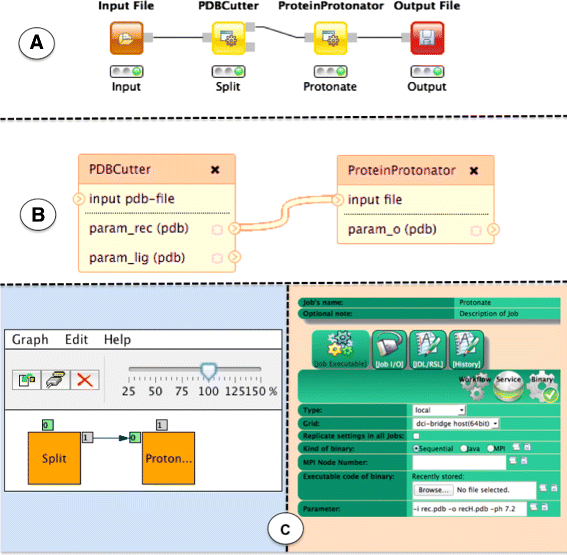
Designing a workflow in gUSE entails two steps: creation of an abstract graph, and a node-per-node configuration of the concrete. Creation of the abstract graph is achieved via a Java WebStart[25] application that is launched from WS-PGRADE, but is executed on the user’s computer. At this point, users are able to provide only application domain information. After saving the abstract graph, users would direct their web browser back to WS-PGRADE, open the concrete for editing, and configure each task comprising the workflow separately. The configuration entails details such as provision of the required command line arguments to execute each task. Since gUSE offers interfaces to several middlewares, it is possible to execute tasks of the same workflow on different DCIs. The possible complexity of workflows that could be executed by gUSE is reflected in the several available fields on the task configuration windows presented to the user while configuring the concrete (see Fig. 6). The two-step creation of workflows (i.e., creation of the abstract graph and creation/configuration of the concrete, as depicted in Fig. 6), combined with the steep learning curve that gUSE poses to new users is an aspect that might intimidate users without much technical experience.
Due to the diversity of workflow engines, a variety of workflow representations has arisen. This disparity of representations poses a challenge to scientists who desire to reuse workflows. Ideally, a scientist would design and test a workflow only once, and it would be possible to execute it on any workflow engine on a given DCI. Built on this principle, the Sharing Interoperable Workflow for Large-Scale Scientific Simulation on Available DCIs project[26] (SHIWA) allows users to run previously existing workflows from different platforms on the SHIWA Simulation Platform. However, privacy concerns might give scientists second thoughts about executing their workflows and uploading their sensitive data on the SHIWA Simulation Platform. Tavaxy[8], focusing on genome comparison and sequence analysis, was created to enable the design of workflows composed of Taverna and Galaxy sub-workflows, and other workflow nodes in a single environment.
There is a clear overlap between the functionalities of the mentioned workflow engines. All offer royalty-free workflow design and execution. However, based on feedback from users and experience in our research group, we believe that the KNIME Analytics Platform is an accessible workflow editor, although it lacks on computing power. On the other hand, again based on experience and feedback, we see gUSE as a great back-end framework that taps into several DCIs, but we have found that its workflow editing capabilities pose a steep learning curve to its user base.
In this paper we present work that bridges the gap between the KNIME Analytics Platform and gUSE. Our work will surely help adopters to significantly reduce the time spent designing, creating and executing repeatable workflows on distributed HPC resources.
Workflow representation
Formal representation
Workflows can be represented using Petri nets.[27][28] Petri nets are directed bipartite graphs containing two kinds of nodes: "places" and "transitions."
A "place" represents a set of conditions that must be fulfilled for a transition to occur. Once a place has satisfied all its conditions, it is enabled. "Transitions" represent actions that affect the state of the system (i.e., copy a file, perform a computation, modify a file).
Places and transitions are connected by edges called "arcs." No arc connects two nodes of the same kind (i.e., this restriction is precisely what makes Petri nets bipartite graphs). Arcs represent transitions’ pre- and postconditions. In order for a transition to take place, all of its preceding places must be enabled (i.e., all of the conditions of preceding places must be satisfied). Conversely, when a transition has been completed, a postcondition is satisfied, influencing the state of subsequent places to which this transition is connected to.
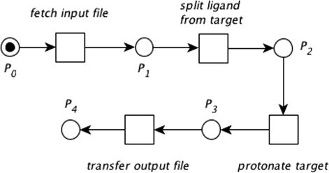
Whenever a place’s condition is satisfied, a token is depicted inside the corresponding place. Figure 3 depicts a simple computer process in which a molecule contained in an input file will be modified by adding any missing hydrogen atoms (i.e., the molecule will be protonated).
|
High-level representation
There are several alternatives to represent workflows in a platform-independent way. Yet another Workflow Language (YAWL)[29] was created after extensive analysis and review of already existing workflow languages in order to identify common workflow patterns and develop a new language that could combine the strengths and overcome the handicaps of other languages. The Interoperable Workflow Intermediate Representation (IWIR)[30] is a standard adopted by several workflow engines and is the language describing workflows in the SHIWA Simulation Platform.[26] More recently a group of individuals, vendors and organizations joined efforts to create the Common Workflow Language (CWL)[31] in order to provide a specification that enables scientists to represent workflows for data-intensive scientific tasks (e.g., mass spectrometry analysis, sequence analysis).
For the sake of clarity and brevity, literature commonly depicts workflows as directed acyclical graphs, in which each vertex represents a place together with its pre- and postconditions (i.e., the preceding and following transitions).[32] Each of the vertices is labelled, has a unique identifier and represents a task to be performed. Furthermore, each of the tasks in a workflow can receive inputs and can produce outputs. Outputs of a task can be channeled through another task as an input. An edge between two nodes represents the channeling of an output from a task into another. Edges determine the logical sequence to be followed (i.e., the origin task of an edge has to be completed before the destination task of an edge can be performed). A task will be executed once all of its inputs can be resolved. Workflow tasks are commonly referred by workflow systems as "nodes" or "jobs," and in this manuscript we will use these terms interchangeably.
Workflow abstraction
Workflows contain three different dimensions or abstraction layers, namely, "case," "process" and "resource" dimensions.[27] Mapping these dimensions into concepts used on distributed execution workflow systems, we find that:
- The "case" dimension refers to the execution of a workflow (i.e., a single run).
- The "process" dimension, also referred to as the abstract layer[33][34], deals with the application domain (i.e., the purpose of the workflow), therefore, technical details such as architecture, platform, libraries, implementation, programming language, etc., are hidden in this dimension.
- The "resource" dimension, often called the concrete layer[33][34], encompasses the hardware and software used to execute the desired process; questions such as "How many processors does a task require?", "Which software running on which device will perform a certain task?", "What are the provided parameters for a specific task?", etc. must be answered in this layer.
Given that the focus of our work is distributed workflows, we prefer the use of the "abstract"/"concrete" terminology throughout this document. Figure 4 depicts the abstract layer of the previously introduced protonation process. This workflow is now composed of four tasks (i.e., vertices) and three edges. The task labelled "Input" has no predecessor tasks, therefore this task is the first one to be executed. In comparison, the task labelled "Protonate" depends on the completion of "Split," which in turn depends on the completion of "Input."
|
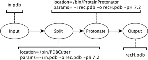
Figure 5, in contrast to Figure 4, shows a possible concrete representation of the presented sample workflow, in which each vertex has been annotated with information needed in order to actually execute the corresponding tasks. While this information varies across workflow execution systems and platforms, the abstract representation of a workflow is constrained only to the application domain and is thus independent of the underlying software and infrastructure. At the concrete layer, the edges not only determine the logical sequence to be followed, but also represent channeled output files. For instance, the "Protonate" task receives an input file from its predecessor, "Split," and generates an output file that will be channeled to the "Output" task.
|
Workflow conversion
As it has been mentioned before, gUSE splits the creation of workflows into two steps: creation of the abstract graph and configuration of the concrete. These steps match the abstract and concrete layers we have discussed in the previous section. Both Galaxy and the KNIME Analytics Platform, in turn, represent workflows without this separation. In order to create a workflow in either Galaxy or the KNIME Analytics Platform, users drag and drop visual elements representing nodes into a workspace. Nodes come pre-configured and commonly execute a single task, therefore the user creates both the abstract and concrete layer at the same time. Inputs and outputs of nodes are visually represented and they can be connected to other nodes. Each node has a configuration dialog in which users can change the default parameters.
It is easy to see how functionally equivalent workflow constructs (e.g., conditional execution of a workflow section, parameter sweep, etc.) are represented differently across workflow engines. Furthermore, engines may offer features that are not available on other workflow systems (e.g., the KNIME Analytics Platform offers elements that are not present neither in gUSE nor in Galaxy, such as "flow variables"[35]). The proper identification and conversion of these elements is important for the conversion, since they play their part in workflow execution. Figure 6 displays a schematic comparison of the implementation of our example workflow across three selected workflow engines, the KNIME Analytics Platform, Galaxy, and gUSE.
|
Due to the variety of workflow systems — we have mentioned only a few instances — it is not surprising that there are several languages and file formats to represent workflows. A first step towards a successful conversion of workflows is to be able to represent the vertices of a workflow (i.e., the tasks, or nodes) in a consistent way across platforms. Once a platform-independent representation of the vertices has been achieved, it is easier to import tasks into several workflow engines with less effort. Conversion of edges is an endeavor that is specific to each of the workflow engines (i.e., a task can be seen as a standalone component, while edges are the result of the collaboration of two or more tasks). Over the course of the last years, we have developed a series of tools enabling workflow interoperability across disparate workflow engines.
Implementation
Conversion of whole workflows can be split into two parts, namely, conversion of vertices and conversion of edges. Vertices represent tasks that take inputs, parameters and produce outputs. This information can be represented in a structured way.
Common Tool Descriptor files (CTD) are XML documents that contain information about parameters, inputs and outputs of a given tool. This information is presented in a structured and human readable way, thus facilitating manual generation for arbitrary tools. Since CTDs are also properly formatted XML documents, it is a trivial matter to parse them in an automated way.[36]
References
- ↑ "Unreliable research: Trouble at the lab". The Economist 409 (8858): 26–30. 19 October 2013. http://www.economist.com/news/briefing/21588057-scientists-think-science-self-correcting-alarming-degree-it-not-trouble. Retrieved 07 July 2015.
- ↑ McNutt, M. (17 January 2014). "Reproducibility". Science 343 (6168): 229. doi:10.1126/science.1250475. PMID 24436391.
- ↑ Greene, C.S.; Tan, J.; Ung, M.; Moore, J.H.; Cheng, C. (2014). "Big data bioinformatics". Journal of Cellular Physiology 229 (12): 1896-900. doi:10.1002/jcp.24662. PMID 24799088.
- ↑ 4.0 4.1 Berthold, M.R.; Cebron, N.; Dill, F.; Gabriel, T.R.; Kötter, T.; Meinl, T.; Ohl, P.; Sieb, C.; Thiel, K.; Wiswedel, B. (2008). "Chapter 38: KNIME: The Konstanz Information Miner". In Preisach, C.; Burkhardt, H.; Schmidt-Thieme, L.; Decker, R.. Data Analysis, Machine Learning and Applications. Springer Berlin Heidelberg. doi:10.1007/978-3-540-78246-9_38. ISBN 9783540782391.
- ↑ 5.0 5.1 Kacsuk, P.; Farkas, Z.; Kozlovszky, M.; Hermann, G.; Balasko, A.; Karoczkai, K.; Marton, I. (2012). "WS-PGRADE/gUSE Generic DCI Gateway Framework for a Large Variety of User Communities". Journal of Grid Computing 10 (4): 601–630. doi:10.1007/s10723-012-9240-5.
- ↑ 6.0 6.1 Blankenberg, D.; Von Kuster, G.; Coraor, N.; Ananda, G.; Lazarus, R.; Mangan, M.; Nekrutenko, A.; Taylor, J. (2010). "Galaxy: A web-based genome analysis tool for experimentalists". Current Protocols in Molecular Biology 19 (Unit 19.10.1–21). doi:10.1002/0471142727.mb1910s89. PMC PMC4264107. PMID 20069535. https://www.ncbi.nlm.nih.gov/pmc/articles/PMC4264107.
- ↑ 7.0 7.1 Missier, P.; Soiland-Reyes, S.; Owen, S.; Tan, W.; Nenadic, A.; Dunlop, I.; Williams, A.; Oinn, T.; Goble, C. (2010). "Chapter 33: Taverna, Reloaded". In Gertz, M.; Ludäscher, B.. Data Analysis, Machine Learning and Applications. Springer Berlin Heidelberg. doi:10.1007/978-3-642-13818-8_33. ISBN 9783642138171.
- ↑ 8.0 8.1 Abouelhoda, M.; Issa, S.A.; Ghanem, M. (2012). "Tavaxy: Integrating Taverna and Galaxy workflows with cloud computing support". BMC Bioinformatics 13: 77. doi:10.1186/1471-2105-13-77. PMC PMC3583125. PMID 22559942. https://www.ncbi.nlm.nih.gov/pmc/articles/PMC3583125.
- ↑ "Admin/Tools/ToolConfigSyntax". Galaxy Project. 19 June 2015. https://wiki.galaxyproject.org/Admin/Tools/ToolConfigSyntax. Retrieved 28 July 2015.
- ↑ "Galaxy Tool Shed". Center for Comparative Genomics and Bioinformatics - Penn State. https://toolshed.g2.bx.psu.edu/. Retrieved 07 July 2015.
- ↑ Moreau, L.; Clifford, B.; Freire, J. et al. (2011). "The Open Provenance Model core specification (v1.1)". Future Generation Computer Systems 27 (6): 743–756. doi:10.1016/j.future.2010.07.005.
- ↑ Goble, C.; Bhagat, J.; Aleksejevs, S. et al. (May 2010). "myExperiment: a repository and social network for the sharing of bioinformatics workflows". Nucleic Acids Research 38 (Supplemental 2): W677–W682. doi:10.1093/nar/gkq429.
- ↑ "KNIME: Open for Innovation". KNIME.org AG. http://www.knime.org/. Retrieved 29 June 2015.
- ↑ "New Node Wizard". Developer Guide. KNIME.org AG. https://tech.knime.org/new-node-wizard. Retrieved 06 July 2015.
- ↑ "Community Contributions". KNIME Community. KNIME.org AG. https://tech.knime.org/community. Retrieved 07 July 2015.
- ↑ "KNIME Cluster Execution". Products. KNIME.org AG. https://www.knime.org/cluster-execution. Retrieved 06 July 2015.
- ↑ "KNIME Server - The Heart of a Collaborative KNIME Setup". Products. KNIME.org AG. https://www.knime.org/knime-server. Retrieved 06 July 2015.
- ↑ Christensen, E.; Curbera, F.; Meredith, G.; Weerawarana, S. (15 March 2001). "Web Services Description Language (WSDL) 1.1". World Wide Web Consortium. https://www.w3.org/TR/wsdl.
- ↑ Gottdank, T. (2013). "gUSE in a Nutshell" (PDF). MTA SZTAKI Laboratory of Parallel and Distributed Systems. http://sourceforge.net/projects/guse/files/gUSE_in_a_Nutshell.pdf/download.
- ↑ 20.0 20.1 20.2 "DCI Bridge Administrator Manual - Version 3.7.1" (PDF). MTA SZTAKI Laboratory of Parallel and Distributed Systems. 12 June 2015. http://sourceforge.net/projects/guse/files/3.7.1/Documentation/DCI_BRIDGE_MANUAL_v3.7.1.pdf/download.
- ↑ Anjomshoaa, A.; Brisard, F.; Drescher, M. et al. (7 November 2005). "Job Submission Description Language (JSDL) Specification, Version 1.0" (PDF). Global Grid Forum. https://www.ogf.org/documents/GFD.56.pdf.
- ↑ Romberg, M. (2002). "The UNICORE Grid Infrastructure". Scientific Programming 10 (2): 149–157. doi:10.1155/2002/483253.
- ↑ "IBM Spectrum LSF". IBM Corporation. 2012. http://www-03.ibm.com/systems/spectrum-computing/products/lsf/index.html.
- ↑ "HPC Products". Adaptive Computing. http://www.adaptivecomputing.com/products/hpc-products/. Retrieved 06 July 2015.
- ↑ "Java SE Desktop Technologies - Java Web Start Technology". Oracle Corporation. http://www.oracle.com/technetwork/java/javase/javawebstart/index.html. Retrieved 03 July 2015.
- ↑ 26.0 26.1 Terstyanszky, G.; Kukla, T.; Kiss, T.; Kacsuk, P.; Balasko, A.; Farkas, Z. (2014). "Enabling scientific workflow sharing through coarse-grained interoperability". Future Generation Computer Systems 37 (7): 46–59. doi:10.1016/j.future.2014.02.016.
- ↑ 27.0 27.1 Van der Aalst, W.M.P. (1998). "The application of petri nets to workflow management". Journal of Circuits, Systems and Computers 8 (1): 21. doi:10.1142/S0218126698000043.
- ↑ Peterson, J.L. (1981). Petri Net Theory and the Modeling of Systems. Prentice Hall. pp. 290. ISBN 9780136619833.
- ↑ Van der Aalst, W.M.P.; ter Hofstede, A.H.M. (2005). "YAWL: Yet Another Workflow Language". Information Systems 30 (4): 245–275. doi:10.1016/j.is.2004.02.002.
- ↑ Plankensteiner, K.; Montagnat, J.; Prodan, R. (2011). "IWIR: A language enabling portability across grid workflow systems". WORKS '11: Proceedings of the 6th Workshop on Workflows in Support of Large-Scale Science: 97–106. doi:10.1145/2110497.2110509.
- ↑ "Common Workflow Language". The CWL Project. http://www.commonwl.org/. Retrieved 03 July 2015.
- ↑ Salimifard, K.; Wright, M. (2001). "Petri net-based modelling of workflow systems: An overview". European Journal of Operational Research 134 (3): 664–676. doi:10.1016/S0377-2217(00)00292-7.
- ↑ 33.0 33.1 Deelman, E.; Blythe, J.; Gil, Y. et al. (2003). "Mapping abstract complex workflows onto grid environments". Journal of Grid Computing 1 (1): 25–39. doi:10.1023/A:1024000426962.
- ↑ 34.0 34.1 Yu, J.; Buyya, R. (2005). "A taxonomy of scientific workflow systems for grid computing". ACM SIGMOD Record 34 (3): 44–49. doi:10.1145/1084805.1084814.
- ↑ "Flow Variables". KNIME Wiki. KNIME.com AG. https://tech.knime.org/wiki/flow-variables. Retrieved 26 October 2015.
- ↑ "Workflow Conversion: Conversion of workflows across workflow systems". GitHub. http://workflowconversion.github.io/.
Notes
This presentation is faithful to the original, with only a few minor changes to presentation. In some cases important information was missing from the references, and that information was added. The original citation #1 was a mix of two different sources, and it has been corrected here to refer in full to the correct citation from The Economist. The original citation #47 got bumped up to 19 due to mandatory wiki ordering, bumping other original citation numbers down one. The original citation #30 (now 31) had an erroneous URL, which was corrected. An additional reference was added concerning "Common Tool Descriptor files" at 36, bumping original citations afterwards down two. Figure 6 has been moved slightly to a more logical place in the article.
