Journal:Development of a smart laboratory information management system: A case study of NM-AIST Arusha of Tanzania
| Full article title | Development of a smart laboratory information management system: A case study of NM-AIST Arusha of Tanzania |
|---|---|
| Journal | International Journal of Advances in Scientific Research and Engineering |
| Author(s) | Mwambe, Edson; Wangere, Joseph N.; Flavian, Daudi; Sinde, Ramadhani |
| Author affiliation(s) | Nelson Mandela African Institution of Science and Technology |
| Primary contact | Email: mwambee at nm-aist dot ac dot tz |
| Year published | 2022 |
| Volume and issue | 8(4) |
| Page(s) | 1–14 |
| DOI | 10.31695/IJASRE.2022.8.4.1 |
| ISSN | 2454-8006 |
| Distribution license | Creative Commons Attribution-NonCommercial 4.0 International |
| Website | https://ijasre.net/index.php/ijasre/article/view/1500 |
| Download | https://ijasre.net/index.php/ijasre/article/view/1500/1921 (PDF) |
Abstract
Testing laboratories in higher learning institutions of science, technology, and engineering are used by institutional staff, researchers, and external stakeholders in conducting research experiments, sample analysis, and result dissemination. However, there exists a challenge in the management of laboratory operations and processing of laboratory-based data. Operations carried out in the laboratory at Nelson Mandela African Institution of Science and Technology (NM-AIST), in Arusha, Tanzania—where this case study was carried out—are paper-based. There is no automated way of sample registration and identification, and researchers are prone to making errors when handling sensitive reagents. Users have to physically visit the laboratory to enquire about available equipment or reagents before borrowing or reserving those resources. Additionally, paper-based forms have to be filled out and handed to the laboratory manager for approval. These manual operations make it difficult to keep track of expiry dates of reagents, stock remaining, storage conditions, software licenses, tools, and data regarding borrowed equipment, as these facets lack automated notification mechanisms.
This study, therefore, was carried out to investigate the development of a smart laboratory information management system (LIMS) integrated with internet of things (IoT) devices, a wireless sensor network (WSN), and radio frequency identification (RFID) technology for real-time monitoring of sample and reagents storage conditions, as well as digital sample identification and tracking. A web application was developed to allow remote access to laboratory information by users. Based on the performance test, it is concluded that WSNs can be integrated with IoT devices to automate recurring tasks in laboratories, aid in monitoring, and eliminate paper-based record keeping.
Keywords: radio frequency identification, wireless sensor network, internet of things, MQTT, ZigBee protocol, ThingSpeak, laboratory information management system
Introduction
Background
Higher learning institutions of science, technology, and engineering conduct experiments in testing laboratories. According to the Oxford Learner’s Dictionary, a laboratory is a building or a part of a building or any other place set aside and equipped for conducting scientific experiments or investigations, in order to develop new products. These testing laboratories are accessible to institutional staff, researchers, and external stakeholders. The Nelson Mandela African Institution of Science and Technology (NM-AIST), based in East Africa (Arusha, Tanzania), has one such testing laboratory that is subdivided into three subsections. Each subsection deals with a different thematic research focus area and is led by a section head. The flow of information in testing laboratories is complex, from sample registration to assigning the sample to an analyst, recording the sample results for each parameter tested, and relaying the results back to the client or researcher. Conventional paper-based approaches for recording all this information are not efficient. A lot of time is bound to be wasted following up on paperwork, and crucial details might be missed or lost in the process. There is therefore a need to aggregate laboratory information on a single platform that can be accessed remotely in order to guarantee real-time access of laboratory data, as well as automate manual processes to increase efficiency, speed, and accuracy. This study therefore proposes a web-based smart laboratory information management system (LIMS) integrated with wireless sensor network (WSN) technology, internet of things (IoT) devices, and radio frequency identification (RFID) to streamline laboratory operations and consolidate all data on a single platform for easy accessibility and tracking.
Problem statement
There exists a challenge in the management of most testing laboratories, in that operations are carried out manually. There is no established mechanism of sample identification, and researchers are prone to making errors when handling sensitive reagents. If users need to borrow laboratory equipment, they have to physically visit the laboratory office, enquire about the availability of equipment, and manually fill out a paper-based form before handing it to the laboratory manager for approval. Due to such manual operations, it is difficult to keep track of expiry dates of reagents, remaining stock, software licenses, tools, data regarding borrowed items, and more. It is therefore in light of the aforementioned setbacks that this study was carried out to investigate the development of a smart LIMS to automate processes in testing laboratories, enabling researchers to plan activities.
Objectives and research questions
The main objective of this research was to investigate the development of a smart LIMS. The specific objectives were:
- Determine and gather requirements for the design and development of a smart LIMS.
- Design and develop a smart LIMS based on those requirements.
- Validate the developed system.
A series of research questions tie into those objectives:
- What are the requirements for developing a smart LIMS?
- How should the smart LIMS be designed and developed?
- How will the study ensure the developed system meets the specified user requirements?
Conceptual framework
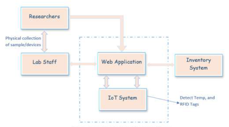
Figure 1 below represents a conceptual framework model that guided the development of the smart LIMS. A web application links an IoT module and inventory module to different user categories, e.g., researchers and laboratory staff.
|
Significance of the study
The implementation of the system is significant in the following outlined aspects:
- Reduction of overhead in the reporting and management processes within laboratories
- Enabling of a central database of all laboratory data in order to digitize operations
- Minimizing operational costs of the laboratory
- Facilitating enforcement of laboratory policies, rules, and standard operating procedures
- Facilitating appropriate and timely calibration of laboratory instruments
- Easy monitoring of inventory, including equipment, samples, supplies, and reagents
Literature survey
A LIMS is a database software application used to acquire, store, analyze, manage, and monitor data in a testing laboratory. The LIMS improves laboratory workflow and productivity by managing the data of samples, reagents, laboratory equipment, analyses, and other activities and stakeholders. A LIMS can act as a single repository of all laboratory information and reduce the communication gaps among the laboratory manager, quality assurance manager, and other stakeholders.[1]
Different researchers have previously attempted to address the automation and digitization of laboratories. We critically analyzed different research to identify gaps and inconsistencies. For example, an RFID-based functioning model for managing laboratory inventory was developed by Hazura et al.[2] RFID is a wireless, contactless identification technology that does not require line of sight. The technology operates in both the low-frequency and ultra-high-frequency RFID standards. However, in their proposed model, a control unit was used to relay data between a 13.56-megahertz (MHz) micro RFID reader and a programmable integrated circuit (PIC), before then sending the data to a computer. The drawback of their proposed solution was a lack of a mechanism for remote or wireless accessibility to the system.
In another study, Hsieh et al.[3] developed an IoT-based smart laboratory administrator system for intrusion and sound detection, as well as monitoring temperature and controlling laboratory access. The system employed OpenCV technology to detect invasion of objects and an Arduino microcontroller with IoT sensors to collect environmental sounds and temperature. The system detected movement, temperature, and voice in real-time and sent immediate messages through an application or email. The limitation of the study, however, was the use of a quick response (QR) code to manage the inventory through a mobile application. The QR code requires line of sight, needs objects to be scanned one by one, and are read-only with a short scanning range.
A system to manage laboratory information and track large amounts of DNA sequencing data was developed by Vu et al.[4] The system employed barcode technology to label the sequenced samples and track experimental procedures. However, sample parameters were still manually fed into the system, which could be prone to error and result in lack of validated data.
Another laboratory equipment management system based on RFID technology was developed for colleges and universities by Zhang and Reha.[5] The system was customized to monitor and track laboratory equipment in real time. It was based on RFID technology, which is superior over other identification technologies because it is automatic, contactless, has a strong ability to be adaptable in demanding environments, and possesses a high data capacity, up to 116 bytes of data. However, RFID implementations cost more compared to barcode implementations.
RFID is among the more popular technologies used for identification of assets in a laboratory. Wahab et al.[6] developed a study similar to Zhang and Reha, examining a web-based laboratory equipment monitoring system that used RFID technology. The system architecture consisted of an RFID reader, RFID tag, RS232 cable, personal computer, and a local area network (LAN) hub. RFID was tested to be 100% accurate in terms of real-time data capture of outbound and inbound equipment in the database. However, a passive RFID tag with an operating frequency of 125 kilohertz (kHz) was used. Its limitation is short response distance, and the metal shield in the RFID tag can block and interfere with the electromagnetic field produced by the RFID reader, thus preventing the tag from being read properly.
In a different study, a system to manage the maintenance of equipment was developed based on mobile two-dimensional (2D) barcode and RFID technology. In the study, it was demonstrated that both RFID and barcode systems can be used on the same equipment. Both 2D barcode and RFID technologies store and provide information. However, RFID tags are easier and faster to read compared to 2D barcodes. In terms of cost, 2D barcodes are cheaper than RFID.[7]
Another RFID system was developed by Ma and Wang to manage and track students’ experiments. RFID was selected over other technologies such as magnetic cards due to being contactless, robust, having high data reading speed, being user friendly, and demonstrating an ability to read multiple tags simultaneously.[8]
RFID technology has also been employed in the development of a library system for automating activities related to the borrowing, renewal, and return of books. The system employs GSM technology to alert the users on the return due date. The system is efficient in terms of speeding up the processes of searching, borrowing and returning books. However, users cannot access the system remotely.[9]
More recent studies have focused on RFID technology due to its superior features over other identification technologies in terms of long response distance range, longer lifespan, reusability, and robustness. In the reviewed studies, the systems were implemented to be accessed locally when a client is in the same LAN. Based on functionality, the studies focused primarily on laboratory equipment and not the management of samples, reagents, and analytical data. This study therefore was carried out to bridge the gaps identified in the previous works.
Materials and methods
Study area and scope
This study was carried out in the United Republic of Tanzania, whereby the NM-AIST was used as a case study. The scope entailed the development of a web-based smart LIMS that integrated with RFID technology for scanning and tracking samples, as well as an IoT module for real-time monitoring of sample storage conditions (i.e., humidity and temperature).
Data collection method
Primary data was collected from laboratory staff, management, and researchers using group discussions, observation, and face-to-face interviews. Secondary data was collected from policy documents, journal articles, research reports, articles, websites, and white papers.
System requirements
The system requirements were categorized into both software requirements and hardware requirements. The software requirements were tabulated as represented in Table 1.
| ||||||||||||||||||||||||||||||||
Hardware requirements on the other hand were captured as represented in Table 2. XBee S2C modules were selected due to their range of more than 60 meters when indoors and up to 1200 meters when outdoors, with a data rate of up to 250,000 bits per second. They operate using the IEEE 802.15.4 technical standard for low-rate wireless personal area networks, within the 2.4GHz unlicensed industrial, scientific, and medical (ISM) band. Communication peripherals include a Serial Peripheral Interface (SPI) and universal asynchronous receiver-transmitter (UART) interfaces.[10]
| ||||||||||||||||||||||||||||||||||||||
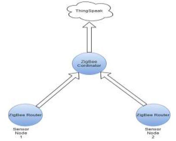
The study’s proposed ZigBee topology is as illustrated in Figure 2, consisting of router nodes and a coordinator node.
|
System development approach
The Agile software development methodology was adopted in the development phase of this study due to the short development cycles in terms of iterations, as well as integrated testing throughout the entire lifecycle of the project. Extreme programming (XP) was particularly used due to its ability to speed up development within the limited timeframe of three months, as well as its emphasis on producing high-quality software, ensuring the small team has high-quality outcomes.
System design
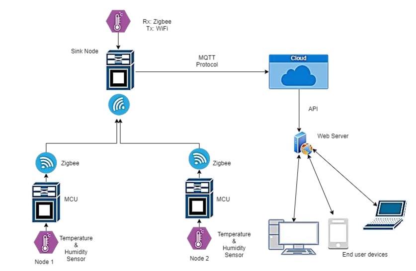
The design framework consisted of a web-based application integrated with an IoT module, made up of a WSN, ThingSpeak Cloud, and an RFID module. The WSN was responsible for collection of data regarding sample and reagents storage conditions, i.e., temperature and humidity. The overall system architectural design is represented in Figure 3.
XBee S2C modules were integrated with STM32F103C8T6 microcontroller boards and an AM2303 temperature-humidity sensor to form sensor nodes. Each sensor was configured to transmit both temperature and humidity values as bytes to a coordinator XBee module connected to an ESP32 microcontroller. The ESP32 microcontroller was configured to convert the temperature and humidity from bytes to float values and then transmit that information to ThingSpeak Cloud using Wi-Fi. The smart LIMS web application was configured to fetch the temperature and humidity graphs for each node from the cloud using an application programming interface (API) provided by ThingSpeak Cloud.
|
Requirements were modeled using Unified Modeling Language (UML). Initially, the gathered requirements were modeled into a use-case diagram, with the main actors being the laboratory manager, quality assurance officer, laboratory staff categorized as section heads, laboratory engineers, and laboratory scientists.
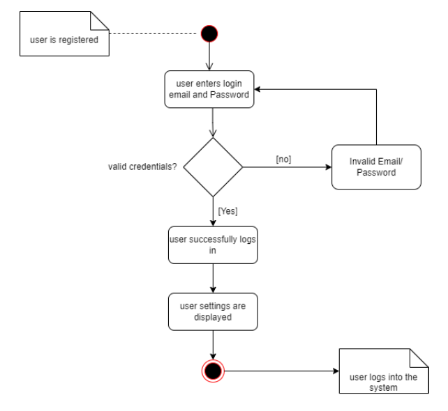
Activity diagrams were modeled to represent the different activities within the system. Figure 4 provides an example of these activity diagrams, depicting the sequence of activities involved in user log-in.
|
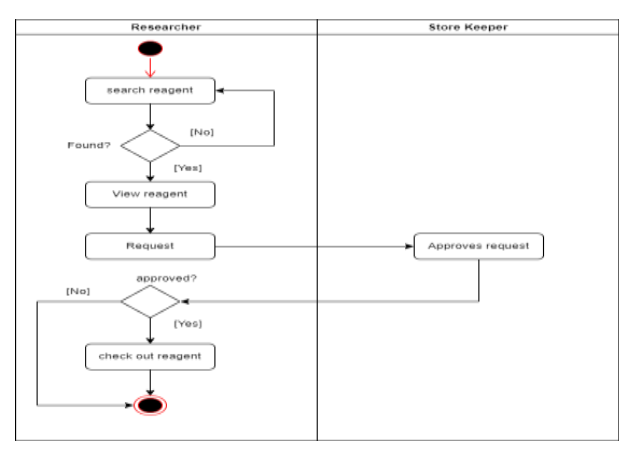
After successful log-in, there are different activities a user can perform depending on the level of access. Figure 5 provides an example of these logged-in activities, depicting the activity diagram for requesting reagents.
|
Simulation
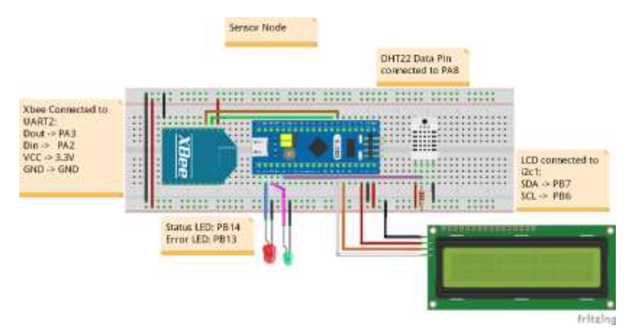
The hardware prototype design was first simulated using software, mainly Fritzing and KiCad. The simulation results enabled the actual hardware implementation to minimize risk of errors and hardware fault, which bears cost implications. Figure 6 represents the design of the sensor node, as captured using Fritzing software.
|
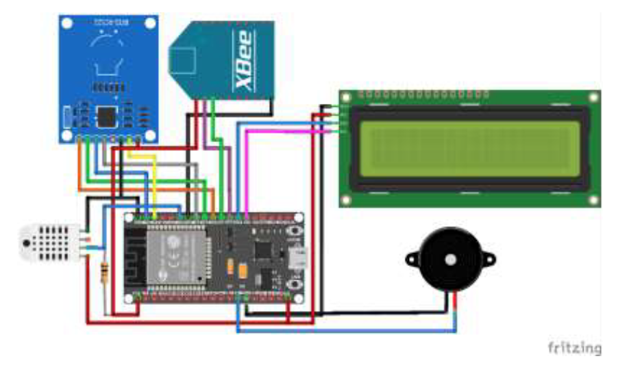
The sensor node design as represented in Figure 6 was replicated to produce two sensor nodes. Additionally, the coordinator node using the ESP32 microcontroller was designed, as captured in Figure 7.
|
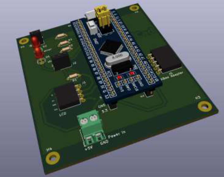
After experimental set-up was tested using breadboards, as presented by Fritzing diagrams in Figures 6 and 7, the circuit schematic design and printed circuit board (PCB) were designed using KiCad software version 5. KiCad was selected because it is open-source and has all the full features of a professional computer-aided design tool—ranging from schematic capture and PCB layout to three-dimensional modeling and visualization of the mechanical version of the circuit board—while being free to use and supporting multiple operating systems platforms, whether Windows or Linux. Figure 8 illustrates a three-dimensional model of the final printed circuit board for the sensor nodes.
|
Results and discussion
A web application integrated with hardware for storage conditions monitoring, as well as sample registration and tracking, was developed.
Web application
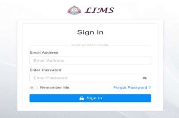
The web application consisted of a log-in page where users first log in. However, the admin is required to add users and give them specific privileges and access levels within the system. The log-in page, as illustrated in Figure 9, requires a registered user email address and a password in order to grant access.
|
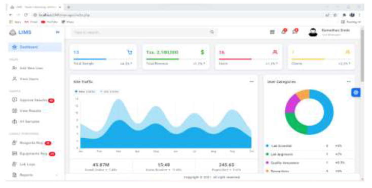
In addition to the log-in page, a dashboard was added, as illustrated in Figure 10, where an authorized user can see an overview of the total number of samples analyzed and even revenue collected.
|
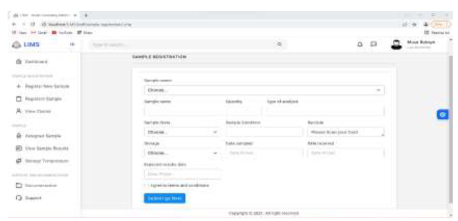
A sample registration page was also added, as shown on Figure 11, where sample parameters are recorded and attached with an RFID tag with a unique identifier after scanning. Details of the sample can later be retrieved by simply placing the sample close to the RFID reader. Each sample is tagged to a particular storage unit that has an identifier in the system.
|
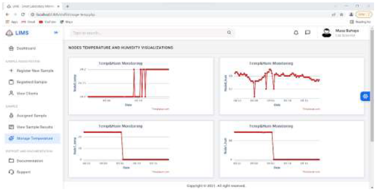
The storage units are constantly monitored by a wireless sensor node for each storage unit. The parameters monitored are temperature and humidity. This information was made available to a user using real-time graphs generated from the data sent by the wireless sensor nodes, as illustrated in Figure 12.
|
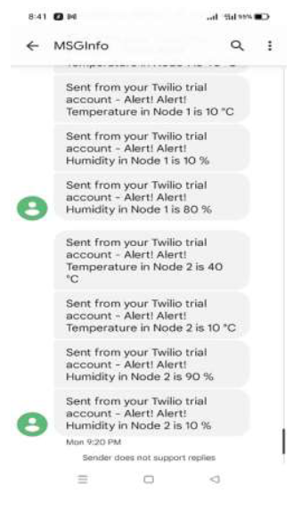
Twilio software was integrated with the system to provide message alerts when temperature or humidity thresholds of the storage conditions are exceeded. Figure 13 shows a sample message alert, as received on a staff member’s mobile phone.
|
Hardware subsystem
The hardware part of the system consisted of two main elements. The first element was a coordinator node, as illustrated in Figure 14 and 15, consisting of an ESP32 Wi-Fi-based microcontroller, an XBee coordinator module, and an RFID reader. This module was responsible for receiving temperature and humidity data of the storage units and transmitting it to the cloud. The RFID reader was responsible for tagging samples with a unique RFID identifier to simplify sample registration and tracking.
|
|
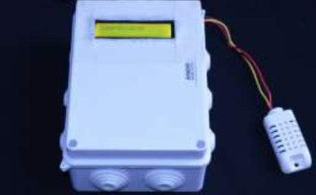
The second hardware element consisted of the sensor nodes, as illustrated by Figure 16, developed by integrating an STM32F103C8T6 microcontroller (“Blue-pill”) with XBee router modules, an LCD module, an AM2303 temperature-humidity sensor, lithium polymer rechargeable batteries, and a DC-DC buck converter module for stepping down the 7.4 volts from the batteries to the 5 volts required by the microcontroller board and sensors.
|
Discussion
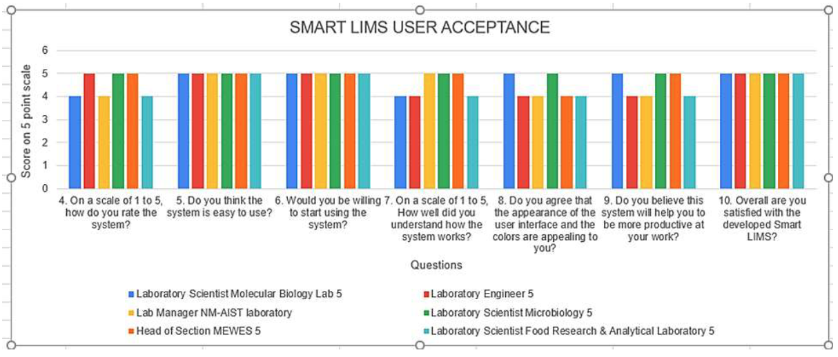
The system was validated by issuing a user acceptance survey, of which six participants from the laboratory department answered. The six participants found the system useful in the streamlining of laboratory information and aggregation of laboratory data on a single platform. On average, when asked to rate the system on a scale of five, all participants rated the system with at least four out of a possible five, as presented in Figure 17. With anticipated growth in research capacity in East Africa and the world at large, there is a need for testing laboratories to digitize their operations and automate tasks as much as possible to increase efficiency and save on operational cost and time. In this advent of IoT devices, there is room for automating nearly all activities by employing the sophisticated technologies that are advancing every day.
|
Conclusion and recommendations
The main objective of this study was to investigate the development of a smart LIMS, by integrating RFID technology with IoT and WSN. A web-based application was developed and integrated with hardware elements consisting of the WSN and an RFID modules. The system was configured to provide real-time notifications regarding sample storage conditions. Customization was done to enable remote accessibility to the system. The developed system was tested with laboratory staff at the NM-AIST. The option for generating reports was included to enable the laboratory manager to view, generate, print, and sign result reports after first level approval by junior staff. Based on the performance test, it is concluded that WSNs can effectively be integrated with IoT devices to automate recurring tasks in laboratories, aid in monitoring, and eliminate paper-based record keeping. Using such a smart LIMS, researchers can better plan research activities.
In the future, this work can be improved by increasing the number of sensors to detect more parameters such as fire, light intensity, and toxic gases. Also, a theft-detection module can be integrated to monitor intrusion and outbound equipment from the laboratories. Machine learning algorithms can be used to analyze the number of experiments and sample analysis carried out periodically and even predict revenue or forecast expected number of samples for analysis. A payment module can be added to facilitate real-time processing of payments by external clients for analysis without the need for them to physically visit the offices. This work can also be extended to other testing laboratories in other sectors such as healthcare, agriculture, and manufacturing and R&D. If the laboratory sections are located far apart from each other, alternative low-power wireless communication technologies should be considered, such as the Long-Range Wide Area Network (LoRAWAN) specification, SIGFOX, etc.
Acknowledgements
This work is financed by the CENIT@EA Project (Centre of Excellence for ICT in East Africa), funded by the German Federal Ministry for Economic Cooperation and Development (BMZ)and implemented by the Deutsche Gesellschaft für Internationale Zusammenarbeit (GIZ) and the German Academic Exchange Service (DAAD). Many thanks to the laboratory scientists, laboratory engineers, and laboratory manager at NM-AIST for their participation in this research and offering technical advice. We would also like to acknowledge the NM-AIST for availing research facilities throughout the course of this study.
Conflict of interest
None stated.
References
- ↑ Schmieder, Florian; Polk, Christoph; Gottlöber, Felix; Schöps, Patrick; Sonntag, Frank; Deuse, Ronny; Jede, Aline; Petzold, Thomas (1 September 2019). "Universal LIMS based platform for the automated processing of cell-based assays" (in en). Current Directions in Biomedical Engineering 5 (1): 437–439. doi:10.1515/cdbme-2019-0110. ISSN 2364-5504. https://www.degruyter.com/document/doi/10.1515/cdbme-2019-0110/html.
- ↑ Hazura, H.; Mardiana, B.; Fauziyah, S.; Zahariah, M.; Hanim, A.R.; Siti Normi, Z. (1 November 2009). "RFID Based Laboratory Management System". 2009 International Conference on Computer Technology and Development (Kota Kinabalu, Malaysia: IEEE): 289–291. doi:10.1109/ICCTD.2009.176. ISBN 978-0-7695-3892-1. https://ieeexplore.ieee.org/document/5360154/.
- ↑ Hsieh, Nan Kai; Kang, Tsan Ching; Chen, Tzer Long; Chang, Jhih Chung; Wang, Min Chien; Chen, Tzer Shyong; Chung, Yu Fang (12 December 2020). "The Implementation of IoT-based Smart Laboratory Management System" (in en). Proceedings of the 2020 ACM International Conference on Intelligent Computing and its Emerging Applications (GangWon Republic of Korea: ACM): 1–3. doi:10.1145/3440943.3442721. ISBN 978-1-4503-8304-2. https://dl.acm.org/doi/10.1145/3440943.3442721.
- ↑ Vu, Thuy Duong; Eberhardt, Ursula; Szöke, Szániszló; Groenewald, Marizeth; Robert, Vincent (25 June 2012). "A laboratory information management system for DNA barcoding workflows" (in en). Integrative Biology 4 (7): 744–755. doi:10.1039/c2ib00146b. ISSN 1757-9708. https://academic.oup.com/ib/article/4/7/744/5204443.
- ↑ Zhang, Renshang; Reha, Ahmed Oulad (31 December 2014). "RFID-Based Logistics Technology of Laboratory Equipments in University" (in en). The Open Electrical & Electronic Engineering Journal 8 (1): 615–619. doi:10.2174/1874129001408010615. ISSN 1874-1290. https://openelectricalandelectronicengineeringjournal.com/VOLUME/8/PAGE/615/.
- ↑ Wahab, Mohd Helmy A; Kadir, Herdawatie A; Tukiran, Zarina; Tomari, Md Razali; Mutalib, Ariffin A; Mohsin, M Farhan M; Idrus, Mohd Nazrul Effendy Mohd (1 June 2010). "Web-based laboratory equipment monitoring system using RFID". 2010 International Conference on Intelligent and Advanced Systems (Kuala Lumpur, Malaysia: IEEE): 1–5. doi:10.1109/ICIAS.2010.5716177. ISBN 978-1-4244-6623-8. http://ieeexplore.ieee.org/document/5716177/.
- ↑ Lin, Yu-Cheng; Cheung, Weng-Fong; Siao, Fu-Cih (1 January 2014). "Developing mobile 2D barcode/RFID-based maintenance management system" (in en). Automation in Construction 37: 110–121. doi:10.1016/j.autcon.2013.10.004. https://linkinghub.elsevier.com/retrieve/pii/S0926580513001611.
- ↑ Ma, Shu Qing; Wang, Chuan Jun (1 June 2014). "Design of Laboratory Management System Based on RFID". Advanced Materials Research 945-949: 2689–2692. doi:10.4028/www.scientific.net/AMR.945-949.2689. ISSN 1662-8985. https://www.scientific.net/AMR.945-949.2689.
- ↑ Malipatil, N.; Roopashree, V.; Gowda, R.H.S. et al. (2020). "RFID Based Library Management System". International Journal of Research in Engineering, Science and Management 3 (7): 112–115. https://www.journals.resaim.com/ijresm/article/view/31.
- ↑ "XBee/XBee-PRO S2C Zigbee RF Module" (PDF). Digi International, Inc. October 2020. https://www.digi.com/resources/documentation/digidocs/pdfs/90002002.pdf.
Notes
This presentation is faithful to the original, with only a few minor changes to presentation. Some grammar and punctuation was cleaned up to improve readability. In some cases important information was missing from the references, and that information was added. Tables 1 and 2 were practically unreadable images, but with great effort they were translated into textual tables. Figure 4, claiming to depict a modeled use-case diagram, was entirely unreadable and was not included for this version; this bumped all subsequent figure numbers up one from their original. The original Figures 11–13 are hardly readable but are included nonetheless as they still show placement of UI elements.
